


- 38 -
SORHEA
G-WALL
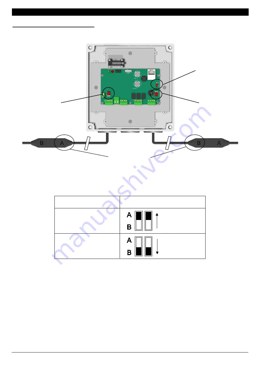
Configuration of the Control Unit:
Each sensor is marked by the letters A and B (visual marker on the sensor).
Identify the markers of the wired sensors on the Control Unit (UG) and position the configuration
switches of cable 1 and cable 2 as shown below:
Marker of the sensors wired
to the Control Unit (UG)
Position of configuration switch of
the detector cable
A
marking
Turn the
switches to A
B
marking
Turn the
switches to B
Cable 1
Configuration
Switch
Sensor 1
Zone 1
Sensor 1
Zone 2
Cable 2
Configuration
Switch
Markings A or B
to identify
1
2
Activate /
Deactivate the
buzzer and the
Ethernet link