SORHEA G-WALL Скачать руководство пользователя страница 27


- 26 - 

SORHEA                     


                            G-WALL


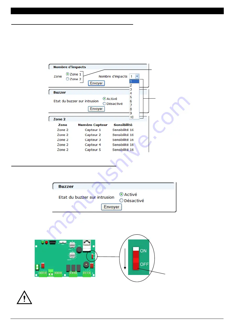
Réglage à distance du nombre d’impacts avant alarme : 
 

  Choisir la zone sur lequel le nombre d’impacts avant alarme va être modifié. 

Sélectionner le nombre d’impacts avant alarme souhaité puis sélectionner « 

Envoyer

 ». 


Nota : pour modifier le nombre d’impacts avant alarme, il faut que les zones de détection soient 
configurées. 


Activation / Désactivation à distance du buzzer : 


 Sélectionner 

« 

Activé

 » ou « 

Désactivé

 » puis « 

Envoyer

 » pour modifier l’état du buzzer. 


Nota : Le changement d’état du switch 1 active ou désactive le buzzer quelque soit l’état du buzzer 

sur le serveur web. 


Le basculement du switch 1 sur « OFF », pour désactiver le buzzer, désactive aussi 
la liaison Ethernet.

Choisir la zone de détection 
pour modification le nombre 
d’impacts avant alarme 

Choisir le nombre 
d’impacts avant alarme 


Switch 1 

Содержание G-WALL

Страница 1: ...DAGE Notice d installation Pages 1 29 CLADDING SHOCK DETECTION SYSTEM Installation manual Pages 30 58 1 rue du Dauphin 69120 VAULX EN VELIN FRANCE T l 33 0 4 78 03 06 10 Fax 33 0 4 78 68 24 61 Site we...

Страница 2: ...de Gestion UG 8 5 2 Raccordement l Unit de Terminaison Raccordement UT UR 10 6 MISE EN SERVICE 12 7 PARAMETRAGE 13 7 1 Proc dure pour entrer en mode param trage 13 7 2 Mode param trage 14 7 3 Sortir...

Страница 3: ...ement UT UR C ble s d tecteur s int grant 20 capteurs PRINCIPALES CARACTERISTIQUES DU PRODUIT Longueur maximale d un syst me 600 m 2 zones de d tection Alimentation 12V DC Horodatage des 1000 derniers...

Страница 4: ...ntrusion Zone 1 1 relais Intrusion Zone 2 1 relais Alarme Technique 2 4 Unit de Terminaison Raccordement UT UR L Unit de Terminaison Raccordement UT UR peut tre utilis e en Unit de Terminaison UT ou e...

Страница 5: ...E 1 zone surveiller 600m max 1 Unit de Gestion UG 1 Unit de Terminaison UT 2 DETECTION 2 ZONES 2 zones surveiller 600m max r partis sur les 2 zones 1 Unit de Gestion UG 2 Unit s de Terminaison UT 3 2...

Страница 6: ...le c ble entre UG et 1er capteur Rallonge 1 UT et capteur Rallonge 2 UR et capteur Rallonge 3 2 capteurs Rallonge 4 Plusieurs rallonges peuvent tre utilis es dans le syst me avec un maximum de 200m c...

Страница 7: ...gabarit ci dessous donne les dimensions de per age 4 2 Installation des Unit s de Terminaison Raccordement 4 3 Installation du c ble d tecteur Installer le c ble d tecteur avec l ensemble de fixation...

Страница 8: ...le bardage 3 Fixer le c ble le long du bardage avec les crochets R partir r guli rement les crochets sur le c ble 4 crochets entre 2 capteurs Passage de poutrelle IPN Vis de fixation Mettre les croche...

Страница 9: ...c ble d tecteur 1 C blage du c ble d tecteur 2 15 Fil rouge du c ble d tecteur 2 16 Fil noir du c ble d tecteur 2 17 Fil jaune du c ble d tecteur 2 18 Fil vert du c ble d tecteur 2 5 6 Alimentation 5...

Страница 10: ...itchs de configuration du c ble 1 et du c ble 2 comme indiqu ci dessous Rep re du Capteur raccord sur l UG Position du switch de configuration du c ble d tecteur Rep re A Basculer les switchs sur A Re...

Страница 11: ...er 1 et le Bornier 2 Le switch de s lection du type de c blage est configurer en fonction du c blage du c ble d tecteur comme expliqu ci apr s Basculer le switch de configuration du mode de fonctionne...

Страница 12: ...type de c blage de l Unit de Raccordement comme indiqu ci dessous Capteur C ble 1 Capteur C ble 2 Position du switch de s lection du type de c blage Rep re A Rep re B Basculer le switch sur Rep re B...

Страница 13: ...uration est termin e Si au bout de 2 min le buzzer ne bip toujours pas et la led rouge clignote toujours se reporter au 9 MAINTENANCE 3 Se reporter au 7 PARAMETRAGE pour modification des param tres de...

Страница 14: ...c dure pour entrer en mode param trage 1 Rep rer la zone pour laquelle le param trage doit tre modifi zone 1 ou zone 2 2 Positionner le switch sur ZONE 1 ou ZONE 2 pour passer en mode configuration l...

Страница 15: ...a sensibilit souhait e Voir tableau R glage de la sensibilit ci dessous Valeur lue sur la s rigraphie de la carte lectronique Nota par d faut la sensibilit est r gl e sur 8 2 Positionner la roue codeu...

Страница 16: ...leur de la sensibilit s lectionn e 1 Exemple Pour un choc d une valeur de 7 Si la sensibilit est r gl e sur 16 l affichage dans l historique sera saturation Si la sensibilit est r gl e sur 10 l affich...

Страница 17: ...re UT UR est en UT voir 5 2 En mode D tection La led de l Unit de Gestion clignote Coupure de c ble Aucune zone n est configur e Se connecter au serveur web onglet Visualisation 11 4 pour rep rer la c...

Страница 18: ...cliquer sur l ic ne Connexions r seau 2 Double cliquer sur l ic ne Connexion au r seau local et s lectionner Propri t s 3 Se positionner dans l onglet G n ral Mettre en surbrillance la ligne Protocole...

Страница 19: ...e sous r seau 255 255 255 0 Valeur imp rative Passerelle 192 168 105 1 Valeur imp rative 5 Valider en cliquant sur OK 11 1 2 Configuration du PC de l utilisateur sous WINDOWS 7 1 Dans Panneau de confi...

Страница 20: ...ier nombre doit tre compris entre 1 et 254 diff rent de 202 Masque sous r seau 255 255 255 0 Valeur imp rative Passerelle 192 168 105 1 Valeur imp rative 6 Valider en cliquant sur OK 11 2 Connexion l...

Страница 21: ...tion dans l url du navigateur Par d faut http 192 168 105 202 4 Saisir le login et le mot de passe de l utilisateur Pages d accueil Internet explorer est une marque Microsoft Corporation Type d acc s...

Страница 22: ...admin ou user 2 Saisir l ancien mot de passe Saisir le nouveau mot de passe puis s lectionner Envoyer 11 3 3 Mise l heure de l Unit de Gestion S lectionner Envoyer pour mettre l heure l Unit de Gesti...

Страница 23: ...uge en alarme 3 Visualisation de l tat des relais Etat du relais Vert hors alarme Rouge en alarme 4 Visualisation du r glage de la sensibilit des capteurs et du nombre d impact avant alarme 5 Visualis...

Страница 24: ...urs en particulier Cliquer sur l onglet R glages La liste des capteurs pr sents dans la zone 1 et dans la zone 2 s affiche en indiquant la sensibilit de chaque capteur Date et heure d apparition de l...

Страница 25: ...6 MISE EN SERVICE tape 2 Attendre la fin de la configuration de la zone pour modifier la sensibilit des capteurs Apr s la Phase de configuration de la zone les champs Capteur et Sensibilit sont dispon...

Страница 26: ...configuration en s lectionnant D tection puis Envoyer Apr s 15 min d inactivit sur les pages web l Unit de Gestion bascule sur le mode s lectionn par le switch de mode de configuration Switch en posi...

Страница 27: ...s de d tection soient configur es Activation D sactivation distance du buzzer S lectionner Activ ou D sactiv puis Envoyer pour modifier l tat du buzzer Nota Le changement d tat du switch 1 active ou d...

Страница 28: ...hors tension l Unit de Gestion R gler la roue codeuse EVENTS sur 6 et la roue codeuse SENSITIVITY sur 9 Appuyer sur le bouton poussoir CONFIG et mettre sous tension l Unit de Gestion en maintenant le...

Страница 29: ...C DC 1A Sortie Intrusion zone 1 par contact NF hors alarme 30V AC DC 1A Sortie Intrusion zone 2 par contact NF hors alarme 30V AC DC 1A Temp ratures de fonctionnement 35 C 70 C Compatibilit lectromagn...

Страница 30: ...n G Wall r f 40710100 Unit de Terminaison Raccordement r f 40710200 C ble d tecteur compos de 20 capteurs r f 40710001 Ensemble de fixation pour c ble G Wall r f 40710002 Conform ment aux directives e...

Страница 31: ...f the Control Unit UG 37 5 2 Wiring of the Termination Link Unit UT UR 39 6 IMPLEMENTATION 41 7 SETTINGS 42 7 1 Procedure to enter into setting mode 42 7 2 Settings Mode 43 7 3 Exit the settings mode...

Страница 32: ...ink Unit s UT UR Detector Cable s integrating 20 sensors MAIN FEATURES Maximum system length 600 m 0 37 miles 2 detection zones 12V DC Power supply Time stamping memory of the last 1000 events Setting...

Страница 33: ...lay Zone 1 1 Intrusion Relay Zone 2 1 Technical Alarm Relay 2 4 Termination Link Unit UT UR The Termination Link Unit UT UR can be used as Termination Unit UT or as Link Unit UR Selection is made usin...

Страница 34: ...E 1 zone to be monitored 300 m 0 19 miles max 1 Control Unit UG 1 Link Unit UT 4 DETECTION 2 ZONES 2 zones to be monitored 300 m 0 19 miles max per zone 1 Control Unit UG 2 Link Unit UT 3 2 Installati...

Страница 35: ...t sensor Extension lead 1 UT and sensor Extension lead 2 UR and sensor Extension lead 3 2 sensors Extension lead 4 Several extension leads can be used in the system with a maximum of 200 m 656 ft accu...

Страница 36: ...late table below contains the dimensions for drilling 4 2 Installing the Termination Link Unit UT UR 4 3 Installation of the detector cable Install the detector cable with the mounting assembly to mou...

Страница 37: ...e bracket to the cladding 3 Attach the cable along cladding using the provided hook Spread regularly the hooks along the cable 4 hooks between 2 sensors Installation at I Beam Fixing screws Attach the...

Страница 38: ...wire of detector cable zone 1 Wiring of detector cable zone 2 15 Red wire of detector cable zone 2 16 Black wire of detector cable zone 2 17 Yellow wire of detector cable zone 2 18 Green wire of dete...

Страница 39: ...configuration switches of cable 1 and cable 2 as shown below Marker of the sensors wired to the Control Unit UG Position of configuration switch of the detector cable A marking Turn the switches to A...

Страница 40: ...lection switch of the cable type is configured according to the wiring of the detector cable as explained below Move the configuration switch to UR to initiate operating mode 1 2 3 4 5 6 7 8 Terminal...

Страница 41: ...ve the selection switch of cable type as shown below Cable 1 sensor Cable 2 sensor Position of the switch for selection of the cable type A marking B marking Turn switch to B marking A marking Turn sw...

Страница 42: ...s finished If after 2 minutes the buzzer still does not beep and the red LED is still blinking refer to 9 MAINTENANCE 3 Please refer to chapter Erreur Source du renvoi introuvable SETTINGS to modify t...

Страница 43: ...before alarm 7 1 Procedure to enter into setting mode 1 Identify the zone where the setting must be adjusted zone 1 or zone 2 2 Move the switch to ZONE 1 or ZONE 2 to enter configuration mode for the...

Страница 44: ...e rotary switch SENSITIVITY on the desired sensitivity See Table Setting the sensitivity below Value read on the serigraphy of the electronic card Note by default the sensitivity is set to 8 2 Set the...

Страница 45: ...9 8 7 6 5 4 3 2 value of sensitivity 1 Example For a shock of a value of 7 If the sensitivity is set to 16 the display will be in the log history saturation If the sensitivity is set to 10 the display...

Страница 46: ...onnect to the web server View tab 11 4 to identify the cut Set the last UT UR is UT see 5 2 In Detection mode The LED for the Control Unit UG blinks Disconnected cable No zones are configured Connect...

Страница 47: ...u on the bottom left of the PC double click on Network connections 2 Double click on Local Area Connection and select Properties 3 Select General Highlight the line Internet Protocol TCP IP by clickin...

Страница 48: ...2 Network mask 255 255 255 0 Mandatory value Gateway 192 168 105 1 Mandatory value 5 Confirm with OK 11 1 2 Configuration of the end user s laptop under WINDOWS 7 1 In Control Panel Start menu on the...

Страница 49: ...omprised between 1 and 254 different from 202 Network mask 255 255 255 0 Mandatory value Gateway 192 168 105 1 Mandatory value 6 Confirm with OK 11 2 Connection to the Control Unit UG 1 The PC is conn...

Страница 50: ...of the Control Unit UG into the browser s URL By default http 192 168 105 202 4 Enter login and password First page Internet explorer is a registered trademark of Microsoft Corporation Access type rea...

Страница 51: ...er 2 Write the former password Write the new password then select Send 11 3 3 Clock settings of the Control Unit UG Select Send to update the time of the Control Unit UG and the connected products to...

Страница 52: ...m on 3 Viewing relay state Relay state Green alarm off Red alarm on 4 Viewing the sensitivity setting of sensors and the number of alarms before impact 5 Viewing technical defaults Technical Default Z...

Страница 53: ...ty of one or more sensors in particular Click on the Settings tab The list of sensors present in the zone 1 and zone 2 is displayed showing the sensitivity of each sensor Date and time event recorded...

Страница 54: ...ne See 6 IMPLEMENTATION step 2 Wait until the end of the configuration zone to modify the sensitivity of the sensors After the configuration phase of the zone the field Sensor and Sensitivity are avai...

Страница 55: ...n mode by selecting Detection then Send After 15 minutes of inactivity on the web pages the Control Unit UG switches to the mode selected by the configuration mode switch Switch position Zone 1 or Zon...

Страница 56: ...detection zones must be configured Remote activated disabled buzzer Select Activated or Disabled then Send to change the status of the buzzer Note By moving switch 1 on OFF the buzzer is deactivate wh...

Страница 57: ...y set IP address Cut the power supply of the Control Unit UG Set the rotary switch EVENTS to 6 and the rotary switch SENSITIVITY to 9 Press the push button CONFIG and power the Control Unit UG holding...

Страница 58: ...zone 1 output by NC contact alarm off 30V AC DC 1A Intrusion zone 2 output by NC contact alarm off 30V AC DC 1A Operating temperature 35 C to 70 C 31 F to 158 F Electromagnetic compatibility Complian...

Страница 59: ...ef 40710200 Detector cable composed of 40 sensors ref 40710001 Mounting Assembly of the detector cable G Wall ref 40710002 In compliance with the European environmental directives this product must no...

Отзывы: