1-23(E)
SX-M700
14
Setting Up the System
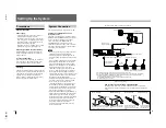
System Connection
This section explains how to connect the system.
Chairman’s unit/delegate’s unit and
interpreter’s unit
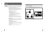
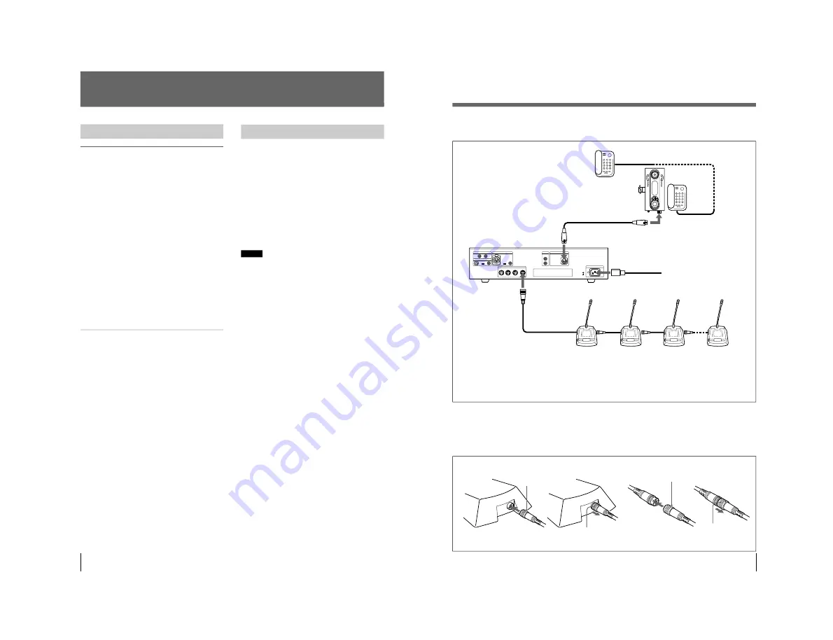
The SX-M100 Control Unit is provided with four
DELEGATE’S/CHAIRMAN’S UNIT connectors.
Up to 15 chairman’s/delegate’s units can be
connected to each of the DELEGATE’S/
CHAIRMAN’S UNIT connectors in serial
connection. The distance between the control unit
and the last chairman’s/delegate’s unit should not
exceed 60 meters (196.8 feet).
Notes
• Be sure to turn off the power of any units before
attempting connection or disconnection.
• The desktop type SX-C100A/D100A and the
desk-mounted SX-C150/D150 are used with this
system.
It is not recommended to mix both combinations.
• When the SX-C100A/D100A is used, the SX-
C700A/C750/D700A/D750 Chairman’s Unit/
Delegate’s Unit, designed for the simultaneous
interpretation conference system, can be
connected to configure this conference system.
However, after the system power is turned on,
the microphone indicator and MIC ON/OFF
buttons of the chairman’s unit and delegate’s unit
continue to blink for about 3 seconds to inform
that the SX-C700A/D700A units for
simultaneous interpretation conference system
have been connected to the conference system.
• If you turn on the system power before
connecting the chairman’s unit/delegate’s unit,
the microphone indicators and MIC ON/OFF
buttons continue to blink and these units cannot
be controlled by the control unit. In such a case,
turn the power off, then back on again.
• When using the DELEGATE’S/CHAIRMAN’S
UNIT connectors of the SX-M100 Control Unit,
attach the dust caps removed from the 20-pin
multi-connectors on the control unit to the 20-pin
multi-connectors on the last unit connected.
If the 20-pin multi-connector has no dust cap,
keep it away from metal tools, such as
screwdrivers to prevent the connector being
inadvertently shorted.
Precautions
Safety precautions
Power supply
• Operate the unit only with a power source as
specified in “Specifications” section.
• Do not drop or place heavy objects on the power
cord. If the power cord is damaged, turn off the
power immediately. It is dangerous to use the
unit with a damaged power cord.
• Disconnect the power cord from the AC outlet by
grasping the plug, not by pulling the cord.
Keep foreign objects out of the cabinet
Dropping flammable or metal objects into the
cabinet, or spilling liquids onto the cabinet can
lead to accidents.
In case of malfunctions
If you notice any unusual sound, smell or smoke,
turn off the power immediately, disconnect the
power supply and contact your Sony dealer.
Cleaning
Clean the cabinet and panels by wiping with a soft,
dry cloth. For severe stains, moisten the cloth with
a small amount of neutral solvent, and finish by
wiping with a dry cloth. Do not use alcohol,
benzine, thinner or volatile liquids, as these may
discolor or damage the cabinet surface.
15
Connecting cord
(supplied with SX-T100)
to AC power source
AC power cord
(supplied with SX-M100)
Other party
CONTROL UNIT
Cable with 20-pin
multi-connector
b)
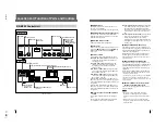
The figure below shows an connection example.
System connection example
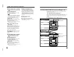
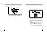
How to connect cables of the SX-C100A/SX-D100A
The figure below shows how to connect and disconnect the 20-pin multi-
connectors of the chairman’s/delegate’s unit and RK-1710/1713 connecting
cables.
MIC
LINE
EXT IN-2
EXT IN-1
LINE OUT
@
TELEPHONE COUPLER
AC IN
1
2
3
4
DELEGATE'S/CHAIRMAN'S UNIT
LINE
MIC
LINE
MIC
LINE
1
2
IN
EXT UNIT
OUT
MIC
SX-T100
TELEPHONE COUPLER
AC IN
DELEGATE’S/CHAIRMAN’S UNIT
a)
SX-C100A
c)
SX-D100A
c)
(Up to 15 units of SX-C100A and
SX-D100A can be connected to one line.)
a) For details of connecting cables, see “How to connect cables” shown below.
b) You can extend the distance between units by using the RK-1710/1713 connecting cable (not supplied).
c) The desk-mounted SX-C150/SX-D150 can also be used in this system. Up to 15 desk-mounted SX-
C150 and SX-D150 units can be connected to one line.
The specially designed cables are used to connect these units to the system.
For details, contact your Sony dealer.
When disconnecting
White mark
White mark
When connecting
With the white mark on the 20-pin
multi-connector facing up, push the
connector home until it clicks.
When disconnecting
When connecting
Grasp the knurled part
of the connector and
pull it towards you.
Meet the white marks on each
connector and push the
connectors each other until they
click.
Grasp the knurled part of the
connector and pull it towards
you.
to output
connector
a)
Telephone line
Содержание SX-M100
Страница 75: ...SX M700 6 12 TMP68301AFR 16 TOSHIBA http getMANUAL com ...
Страница 110: ...8 1 8 1 SX M700 SX M700 M100 BLOCK SX M700 M100 BLOCK SX M700 M100 DIGITAL SECTION 8 BLOCK DIAGRAMS DIGITAL BLOCK ...
Страница 111: ...8 2 8 2 SX M700 SX M700 AUDIO SX M700 BLOCK SX M700 BLOCK AUDIO BLOCK ...
Страница 112: ...8 3 8 3 SX M700 SX M100 BLOCK SX M100 BLOCK SX M100 AUDIO AUDIO BLOCK ...
Страница 113: ...8 4 8 4 SX M700 SX E120 DIGITAL SX E120 BLOCK SX E120 BLOCK DIGITAL BLOCK ...
Страница 114: ...8 5 8 5 SX M700 SX E120 BLOCK SX E120 BLOCK SX E120 AUDIO AUDIO BLOCK ...
Страница 115: ...8 6 8 6 SX M700 SX T100 AU 202 SX T100 BLOCK SX T100 BLOCK AU 202 BLOCK http getMANUAL com ...
Страница 116: ...8 7 8 7 SX M700 SXA 120 BLOCK SXA 120 BLOCK SXA 120 AUDIO CPU 188 BLOCK ...
Страница 120: ......
Страница 126: ......
Страница 128: ......
Страница 130: ......
Страница 132: ......
Страница 136: ......


