1-7(E)
SX-M700
12
INTERPRETER'S UNIT SX-P700
MICROPHONE CHANNEL
MICROPHONE CHANNEL
MONITOR
1
2
3
4
5
6
1
2
3
4
5
6
MONITOR
ORIGINAL
RELAY
VOLUME
MIN
MAX
1
2
3
4
5
6
7
8
9
COUGH CUT
MICROPHONE
ON
ON
OFF
COUGH CUT
SLOW
VOLUME
MIN
MAX
1
2
3
4
5
6
7
8
9
ORIGINAL
RELAY
1
2
3
4
5
6
1
2
3
4
5
6
CONTROL UNIT/INTERPRETER'S UNIT
MAIN
LINE
OUT
SUB
LEVEL
LOW
NORM
MIC IN
Front panel
Left side panel
7
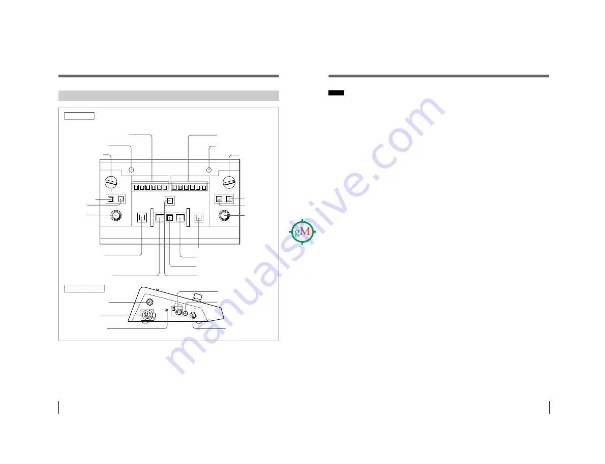
COUGH CUT button
8
MICROPHONE ON button
0
SLOW button
9
MICROPHONE OFF button
!¡
CONTROL UNIT/
INTERPRETER’S UNIT
connector
!™
MIC IN connector
!£
MIC IN LEVEL switch
!§
MAIN headphones
connector
1
MICROPHONE CHANNEL buttons
4
RELAY button
5
ORIGINAL
button
6
VOLUME
control
8
MICROPHONE ON button
7
COUGH CUT button
6
VOLUME
control
5
ORIGINAL
button
4
RELAY button
3
MONITOR
selector
2
Microphone indicator
3
MONITOR selector
1
MICROPHONE CHANNEL
buttons
2
Microphone indicator
!¢
SUB headphones connector
and volume control
!∞
LINE OUT connector
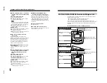
1
MICROPHONE CHANNEL buttons
Press the button corresponding to the channel for
the target language (channel 1 to channel 6) such
that the indicator lights.
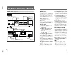
SX-P700 Interpreter’s Unit
Front panel
The interpreter’s unit is designed to be used by two
interpreters. There are two sets of controls
1
to
8
on the left section and right section of the unit.
Their functions are exactly the same. Buttons
9
and
0
are common to both left and right sections.
Either of the two interpreters can use these buttons.
Location and Function of Parts and Controls
13
8
MICROPHONE ON button
Press this button to enable the microphone. The
microphone indicator lights while the microphone
is live. When another interpreter presses his or her
MICROPHONE ON button, this microphone is
disabled.
9
MICROPHONE OFF button
Press the button to disable the microphone such
that the MICROPHONE ON button goes out.
0
SLOW button
Press to request that the speaker speaks slowly.
While the interpreter is holding down this button,
the PRIORITY button on the chairman’s unit
blinks.
Left side panel
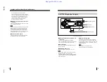
The following connectors and switches
!¡
,
!™
,
!£
,
!¢
and
!§
are located on both sides of the
interpreter’s unit. The LINE OUT connector
!∞
is
provided only on the left side.
!¡
CONTROL UNIT/INTERPRETER’S UNIT
connector (20-pin multi-connector)
Two connectors on the left and right sections have
the same function. Connect to the CONTROL
UNIT/INTERPRETER’S UNIT connector of the
next interpreter’s unit by using the RK-1705/1700
connecting cable (5m or 16.4 feet/10m or 32.8
feet) (not supplied). When the interpreter’s unit is
placed next to the SX-M700 Control Unit, connect
to the INTERPRETER’S UNIT connector of the
control unit.
!™
MIC IN (microphone input) connector
(XLR 3-pin)
Connect a microphone having an XLR connector.
!£
MIC IN LEVEL switch
Selects the output level of the microphone
connected to the MIC IN connector.
NORM (normal): Normally, set the switch to this
position.
LOW: Set the switch to this position when a
microphone having a low output level is being
used.
Notes
• Should you accidentally press the wrong button
while you are interpreting, your voice will be
output on the wrong channel.
• When the system power is turned on or the
power is turned off and back on again, channel 1
is automatically selected (the button of channel 1
automatically lights).
2
Microphone indicator
Lights when the MICROPHONE ON button is
pressed. While this indicator is lit, the
corresponding interpreter’s microphone is enabled.
3
MONITOR selector
Selects the channel of the language to be
monitored when relay interpreting is being
performed. This selector is effective only when the
RELAY button
4
is pressed.
4
RELAY button
Used to perform relay interpreting. Press to
monitor the language selected with the MONITOR
selector
3
through the headphones (the button
lights).
5
ORIGINAL button
Press to monitor the original signal through the
headphones (the button lights).
RELAY button and ORIGINAL button
When the RELAY button is pressed, it lights and
the ORIGINAL button goes out. The interpreter
can then monitor the language selected with the
MONITOR selector
3
. When the ORIGINAL
button is pressed, it lights and the RELAY button
goes out. The interpreter can monitor the original
signal.
When the system power is turned on or the power
is turned off and back on again, the ORIGINAL
button automatically lights.
6
VOLUME control
Adjusts the volume of the main headphones of the
main interpreter.
7
COUGH CUT button
Press to disable the microphone temporarily. The
microphone is disabled and the microphone
indicator
2
does not light for as long as the
interpreter holds down the button.
Содержание SX-M100
Страница 75: ...SX M700 6 12 TMP68301AFR 16 TOSHIBA http getMANUAL com ...
Страница 110: ...8 1 8 1 SX M700 SX M700 M100 BLOCK SX M700 M100 BLOCK SX M700 M100 DIGITAL SECTION 8 BLOCK DIAGRAMS DIGITAL BLOCK ...
Страница 111: ...8 2 8 2 SX M700 SX M700 AUDIO SX M700 BLOCK SX M700 BLOCK AUDIO BLOCK ...
Страница 112: ...8 3 8 3 SX M700 SX M100 BLOCK SX M100 BLOCK SX M100 AUDIO AUDIO BLOCK ...
Страница 113: ...8 4 8 4 SX M700 SX E120 DIGITAL SX E120 BLOCK SX E120 BLOCK DIGITAL BLOCK ...
Страница 114: ...8 5 8 5 SX M700 SX E120 BLOCK SX E120 BLOCK SX E120 AUDIO AUDIO BLOCK ...
Страница 115: ...8 6 8 6 SX M700 SX T100 AU 202 SX T100 BLOCK SX T100 BLOCK AU 202 BLOCK http getMANUAL com ...
Страница 116: ...8 7 8 7 SX M700 SXA 120 BLOCK SXA 120 BLOCK SXA 120 AUDIO CPU 188 BLOCK ...
Страница 120: ......
Страница 126: ......
Страница 128: ......
Страница 130: ......
Страница 132: ......
Страница 136: ......


