background image

65

4-2 HOME Menu


C

h

ap
te

r 4


M

enu

 Se
tt

in

g

s

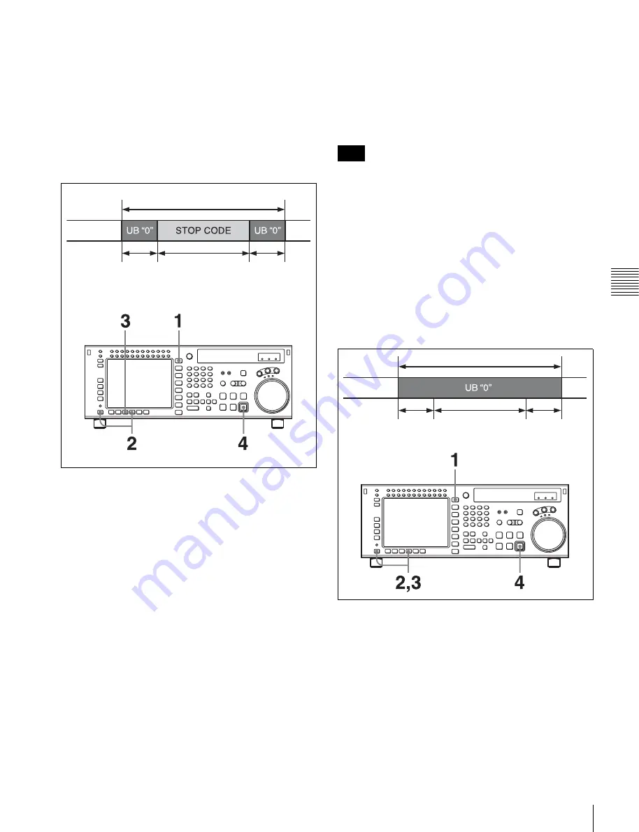
Recording stop codes: 

[F7]

To record stop codes, press the 

[F7]

 (CODE REC) button. 

In PLAY, JOG, or similar mode, cue up to the SOM point, 
and press the REC/EDIT button. With the point at which 
the REC/EDIT button is pressed as the SOM point, after a 
preroll, the recording operation starts, and as shown in the 
figure below, user bits (value 0) and stop code are 
recorded, after which the unit automatically stops. After 
recording is completed, the setting of the 

[F7]

 (CODE 

REC) button is automatically changed to OFF.

1

Press the HOME button.

The HOME menu screen appears.

2

Press the ALT/

[F8]

 (STOP CODE) buttons.

The STOP CODE menu screen appears.

3

Press the 

[F7]

 (CODE REC) button to select “on”.

Pressing the button toggles between “on” and “off”.

4

Press the REC/EDIT button.

To abandon the operation at any point

Press the STOP button.

To specify the recording start position

Press the 

[F5]

 (REC ADJUST) button, to specify how 

many seconds before the SOM point the recording of the 
stop code should start.

To check the recording

Press the PREVIEW/REVIEW button. The tape prerolls to 
the SOM point and playback starts. If the stop code is 

correctly recorded, regardless of the settings of the 

[F2]


(DETECT BEEP) button and 

[F3]

 (DETECT STOP) 

button, a confirmation sound is emitted for 1 second, and 
the unit stops in accordance with the setting of the 

[F4]


(DETECT ADJUST) button. If the unit does not stop even 
after passing the point at which the stop code is recorded, 
repeat the recording operation.

Checking the recording with the PREVIEW/REVIEW 
button is only valid in the stop code menu screen.

Deleting stop codes: 

[F8]

To delete a stop code, press the 

[F8]

 (CODE ERASE) 

button. In stop code detection mode, stop the VTR at the 
stop code you want to delete, and press the REC/EDIT 
button. After prerolling 5 seconds before the stop code 
recording point, the VTR begins the delete operation, and 
as shown in the figure below, user bits (value 0) are 
recorded, after which the unit automatically stops. After 
deletion is completed, the setting of the 

[F8]

 (CODE 

ERASE) button is automatically changed to OFF.

1

Press the HOME button.

The HOME menu screen appears.

2

Press the ALT/

[F8]

 (STOP CODE) buttons.

The stop code menu screen appears.

3

Press the 

[F8]

 (CODE ERASE) button to select “on”.

Pressing the button toggles between “on” and “off”.

4

Press the REC/EDIT button.

Section to insert time code

Tape

3 frames

20 frames

3 frames

Note

Section to insert time code

Tape

3 frames 20 frames (STOP 

CODE before deletion)

3 frames

Содержание HKSR-5803HQ

Страница 1: ...TE RECORDER SRW 5800 FORMAT CONVERTER BOARD HKSR 5001 DIGITAL BETACAM HDCAM PROCESSOR BOARD HKSR 5802 RGB SQ PROCESSOR BOARD HKSR 5803SQ ADVANCED HQ PROCESSOR BOARD HKSR 5803HQ OPERATION MANUAL English 1st Edition Revised 5 ...

Страница 2: ...r moisture does not operate normally or has been dropped To reduce the risk of fire or electric shock do not expose this apparatus to rain or moisture To avoid electrical shock do not open the cabinet Refer servicing to qualified personnel only THIS APPARATUS MUST BE EARTHED When installing the installation space must be secured in consideration of the ventilation and service operation Do not bloc...

Страница 3: ...ts for a digital device pursuant to Subpart B of Part 15 of FCC Rules This device complies with Part 15 of the FCC Rules Operation is subject to the following two conditions 1 this device may not cause harmful interference and 2 this device must accept any interference received including interference that may cause undesired operation For the customers in Canada This Class A digital apparatus comp...

Страница 4: ...g Up the VTR 3 1 Connecting External Equipment 29 3 1 1 Making HD Digital Connections 29 3 1 2 Making NTSC PAL Digital Connections 30 3 1 3 Cascade Connection 31 3 2 Reference Signals 32 3 2 1 Reference Signals for Output Video 32 3 2 2 Reference Signal Connections 33 3 3 Handling Cassettes 34 3 3 1 Recommended Cassettes 34 3 3 2 Inserting and Ejecting Cassettes 35 3 3 3 Preventing Accidental Eras...

Страница 5: ...cord Inhibit Mode REC INH 62 4 2 3 Selecting the Edit Mode and Edit Channel ASSEMBLE INS TC INS VIDEO and INS AUDIO 62 4 2 4 Still Picture Output FREEZE 62 4 2 5 Setting the Preroll Time PREROLL TIME 63 4 2 6 Selecting DMC Playback DMC 63 4 2 7 Setting the Stop Code STOP CODE 63 4 3 TC Menu 67 4 3 1 Setting the Time Data TIMER SEL RESET SET HOLD 68 4 3 2 Setting the Time Code Reader TCR SEL 71 4 3...

Страница 6: ...on DIGOUT EXCHNG 108 4 6 3 Digital Audio Output Signal Source Track Selection SDOUT EXCHNG 108 4 6 4 External Device Audio Edit Preset Command Replace Mode Selection EDIT PRESET REPLACE CHANNEL SELECT 109 4 6 5 External Device Digital Audio Edit Preset Command Replace Mode Selection AUDIO EDIT PRESET REPLACE 110 4 6 6 External Device Analog Audio Edit Preset Command Replace Mode Selection ANALOG A...

Страница 7: ...g 130 6 1 1 Overview of Automatic Editing 130 6 1 2 Setting Switches and Menus 131 6 1 3 Selecting the Edit Mode 132 6 1 4 Selecting Video for Editing 3D Systems Only 132 6 1 5 Setting Edit Points 132 6 1 6 Editing Non audio Data 136 6 1 7 Confirming Edit Points 136 6 1 8 Cuing Up and Prerolling 136 6 1 9 Previewing 137 6 1 10 Modifying Edit Points 137 6 1 11 Performing Automatic Editing 140 6 2 A...

Страница 8: ...g to Prerolling Nos 401 to 169 Items Relating to Recording Protection Nos 501 to 170 Items Relating to the Time Code Nos 601 to 171 Items Relating to the Video Control Nos 706 to 176 Items Relating to the Audio Control Nos 807 to 179 Items Relating to Digital Processing Nos 902 to 185 Items Relating to the Pulldown Control Nos A01 to 191 Items Relating to the HKSR 5804 Nos B01 to 194 Other Items N...

Страница 9: ...04B 005B 006B SMPTE 291M 292M 299M 372M 424M only when the serial number of this unit is 11001 or higher and ARIB STD B4 allowing the BNC coaxial cable to carry one component video signal twelve digital audio channels and time code in time division multiplex this is separated for conversion to parallel data Audio recording can be switched between the digital audio signal multiplexed with the HD SD...

Страница 10: ...tion When the serial number of this unit is 12001 or higher Recording and playback in SQ mode are standard and the HKSR 5803SQ option or HKSR 5803HQ option is not required Recording and playback in HQ mode require the HKSR 5803HQ option To record playback 2048 1080 and 2048 1556 signals the serial number of this unit must be 12001 or higher and the HKSR 5803HQ option is required 1 HQ mode This mod...

Страница 11: ...heads Video and audio channels 1 through 12 signals can be recorded and simultaneously played back to check the recording Internal time code generator and reader The internal time code generator allows you to record time code LTC or user bits together with video and audio signals Time codes LTC or user bits can be read during playback using the time code reader Computer servo system Computer contr...

Страница 12: ...e 10 cue points per page can be set on a total of 10 pages In the Tele File menu you can change the setting for the memory label system Tele File PF1 PF2 Personal Function menus Use these menus to register up to 40 of the most frequently used items from the other menus up to 10 items each can be registered to PF1 ALT PF1 PF2 and ALT PF2 SET UP menu This menu enables the following settings The VTR ...

Страница 13: ... video track during the vertical blanking interval 1 2 Optional Accessories The following accessories can be used with this unit HKSR 5001 Format Converter Board This allows format conversion described below 2 3 pulldown 23 98PsF to 59 94i 24PsF to 60i Conversion between 1080 and 720P 4 2 2 between 4 4 4 Conversion of 4 4 4 to 4 2 2 is possible only when the HKSR 5803SQ or HKSR 5803HQ is additiona...

Страница 14: ...ial number of this unit is 12001 or higher For details on operations regarding this board refer to the Operation Manual supplied with the HKSR 5804 HKDV 900 HD Digital Video Controller This allows you to remotely control the parameters for video signals and image enhancement References In addition to this Operation Manual the following manuals are available Maintenance Manual Volume 1 optional Pro...

Страница 15: ...Lower control panel System set up panel 5 Search control section see page 22 3 Tape transport control section see page 20 2 Editing control section see page 19 1 Menu control section see page 17 System set up panel Access by opening the lower control panel see page 23 Upper control panel 4 Display section see page 20 Lower control panel Serial number lower than 11001 Serial number 11001 or higher ...

Страница 16: ...ted If this indicator remains lit continuously head cleaning or internal inspection is required e EJECT button Pressing this button automatically ejects the cassette after several seconds f Format indicators Digital BETACAM HDCAM HDCAM SR These show the format of the cassette loaded into the unit g REMOTE buttons Press one of the following buttons to select how the VTR is controlled NETWORK 1 This...

Страница 17: ... In the audio playback level adjustment mode this is used to select the channel to be adjusted b MONITOR R buttons Select the audio signal output from the MONITOR OUTPUT R connector This assigns the desired channel to the MONITOR OUTPUT R connector If you assign more than one channel to the same monitor output connector a mixed audio signal is output You can also make this setting using the VTR SE...

Страница 18: ...ion buttons F1 to F10 and shows simultaneously information required for time code display settings and so on 1 E E mode An abbreviation for Electric to Electric mode In this mode video or audio input signals are passed and output only through the VTR s internal circuitry and not through the magnetic conversion system comprising tape and heads f Function buttons Activates the functions in each menu...

Страница 19: ...SFT shift button Press buttons 0 to 5 while holding down this button to input hexadecimal A to F for user bits Use also in combination with other buttons to perform other operations c RCL recall button Press to recall the previous setting etc d CLR clear button Press to clear input data e SET button Press to finalize input data f INPUT CHECK button While you hold down this button the input signal ...

Страница 20: ...results of the edit are played back on the monitor connected to the recorder d REC EDIT recording edit button Press this button while holding down the PLAY button to start recording If you press this button in play mode manual editing begins After setting edit points if you press this button while the AUTO button is lit automatic editing is performed e PLAY button Press to start playback Press thi...

Страница 21: ...respect to reference Page 5 Phase TC TC INPUT DELAY Shows the recording phase of the input time code OFF Recorded in phase with the input video signal 1Frame Recorded one frame delayed with respect to the input video signal LTC OUTPUT Shows the phase of the output LTC LINE Output in phase with the main line HD SDI output FC Output in phase with the FC output Page 6 Meta data HDCAM SR META DATA LIN...

Страница 22: ...button lights and playback at the speed corresponding to the angle of rotation of the search dial is possible The playback speed range depends on the frame frequency of the unit In this mode the search dial clicks at the positions for 0 still picture and 10 times normal playback speed HDCAM Digital Betacam or 8 times normal playback speed HDCAM SR b JOG button Press to select jog mode In this mode...

Страница 23: ...mes normal speed Digital Betacam depending on the setting of the VTR SETUP menu item 107 JOG DIAL RESPONSE The dial does not click Variable speed playback mode Noiseless playback is possible in the range from 0 5 to 1 times normal speed HDCAM SR from 1 to 2 times normal speed HDCAM or from 1 to 3 times normal speed Digital Betacam The speed settings can be changed using the menu The dial clicks at...

Страница 24: ...nector Panel Chapter 2 Locations and Functions of Parts 2 2 Connector Panel 1 ANALOG I O section see page 25 2 DIGITAL I O section see page 27 3 Remote input output section see page 28 4 Power supply see page 28 ...

Страница 25: ...nce video signal of the field frequency selected for the format converter output Select HD or SD with the VTR SETUP menu item A08 FC REFERENCE select When HD is selected input an HD tri level SYNC signal for external synchronization When SD is selected input a video signal with chroma burst VBS or a monochrome video signal VS A loop through connection is possible Set the 75Ω termination switch to ...

Страница 26: ...nal time code generator or time code input to the TIME CODE IN connector To select the output signal use the VTR SETUP menu item 613 TC OUTPUT SIGNAL IN REGENE MODE h CUE OUT cue output connector XLR 3 31 male Outputs cue track audio during HDCAM or Digital Betacam playback There is no cue track on an HDCAM SR tape and therefore no output i TIME CODE IN connector XLR 3 32 female Accepts external t...

Страница 27: ...C CHARA buttons are set to ON in the TC menu the output has time data or other text superimposed on the signal This is only valid when the optional HKSR 5001 format converter board is installed d SD SDI OUT 1 2 MONITOR connectors BNC These output three sets of video audio signals When the ALT F6 CHARA SUPER buttons are set to ON in the TC menu time data or other text data is superimposed on the ou...

Страница 28: ...controller d REMOTE 1 I O 9P connector D sub 9 pin female Use this with the supplied 9 pin remote control cable to connect the unit to another SRW 5000 5500 unit or another HD VTR unit to carry out editing with a BVE series editor BVE 700 2000 9000 9100 e NETWORK 1 connector Used for monitoring the VTR by SNMP or for setting or changing VTR settings by HTTP For safety do not connect the connector ...

Страница 29: ... External Equipment 3 1 1 Making HD Digital Connections This example shows the connections when using an SRW 5000 5500 as player and an SRW 5800 as recorder in 59 94i or 60i mode SRW 5000 5500 Player a 9 pin remote control cable SRW 5800 Recorder a The figure shows the SRW 5500 Video monitor HD serial monitor ...

Страница 30: ...Making NTSC PAL Digital Connections This example shows how to connect two VTRs an SRW 5800 as the player and a DVW 2000 D 1 Component Digital VTR as the recorder SRW 5800 Player BNC cable BNC cable Video monitor NTSC PAL monitor DVW 2000 Recorder 9 pin remote control cable ...

Страница 31: ...ltiple SRW series VTRs together for simultaneous recording On the recording VTRs set the VTR SETUP menu item 613 TC OUTPUT SIGNAL IN REGENE MODE to through Note BNC cable Digital video distributor HKPF 103M SRW 5800 Recorder Video monitor HD serial monitor SRW 5800 Recorder a The figure shows the SRW 5500 SRW 5000 5500 Player a ...

Страница 32: ...EFERENCE select extrn SD extrn HD Is there a signal of the correct frequency on the REF INPUT 1 or 2 a connector Is there a signal of the correct frequency on the REF INPUT 1 or 2 a connector Yes Yes Is there an input signal on the HD SDI INPUT connector Yes No No Synchronization with the reference video signal input to the REF INPUT 1 or 2 a connector Synchronization with the video signal input t...

Страница 33: ...cted You can select the following reference signals from menu item 006 EXTERNAL REFERENCE select extrn HD 1080 59 94i tri level SYNC signal extrn SD 525 black burst signal When the 720 50P system is selected You can select the following reference signals from menu item 006 EXTERNAL REFERENCE select extrn HD 1080 50i tri level SYNC signal extrn SD 625 black burst signal When you have directly conne...

Страница 34: ...hen 2048 1556 25PsF is selected You can select either of the following reference signals in menu item 006 EXTERNAL REFERENCE select extrn HD 1080 50i tri level SYNC signal extrn SD 625 black burst signal 3 3 Handling Cassettes 3 3 1 Recommended Cassettes For recording and playback Use 1 2 inch HDCAM SR cassettes The maximum recording time is as shown in the following table The recording and playba...

Страница 35: ...e cassette insertion slot to prevent users from attempting to load another cassette Ejecting the cassette Press the EJECT button The tape is unthreaded and the cassette is automatically ejected This operation takes a few seconds To cancel ejecting a cassette Press any operation button before the cassette is completely ejected The cassette is loaded again and the operation corresponding to the butt...

Страница 36: ...hen the serial number of this unit is lower than 11001 Push the eject button on the memory card adaptor and pull the Memory Stick out When the serial number of this unit is 11001 or higher Push the Memory Stick in and then pull it out 3 4 1 Notes on Memory Stick Usable type of Memory Stick You can use a Memory Stick PRO with this unit The Memory Stick PRO Duo can also be used but using the Memory ...

Страница 37: ...he Memory Stick to get wet Do not use or store the Memory Stick in a location that is Extremely hot such as in a car parked in the sun Under direct sunlight Very humid or subject to corrosive substances When the Memory Stick access indicator is lit or flashing Data is being read from or written to the Memory Stick at this time Do not shake the product or subject it to shock Do not turn off the pow...

Страница 38: ... Menu on page 113 PF ASSIGN menu list This is a list of menu items which can be registered to the HOME TC VIDEO AUDIO PF1 and PF2 menu screens as well as the screen that is displayed by pressing the ALT button the ALT screen This includes all VTR SETUP menu item Press the F4 PF ASSIGN button in the SET UP menu to display this menu For details on registering items see 4 1 3 Registering Items to the...

Страница 39: ...uently used menu items the settings can be carried out together Registering items 1 Press the SET UP button The SET UP menu appears in the display 2 Press the F4 PF ASSIGN button The PF ASSIGN menu appears in the display 3 Press the F1 PAGE button to select the menu where you wish to register an item The selected menu appears and the items currently registered to the menu appear in the middle of t...

Страница 40: ...up to eight sets of menu settings The contents of all eight VTR memory banks can be stored on a Memory Stick The storing recalling of the contents of VTR memory banks can also be performed through the network For details on Memory Stick use see 4 1 5 Memory Stick Operations on page 42 For details on adding titles to the contents of the VTR memory bank see 4 1 7 Adding Titles to the Data on page 53...

Страница 41: ...lashing cursor bar indicates the storage destination 6 Press the F9 COPY button A message appears in the display asking you to confirm the operation To cancel the storage operation Press the CLR button 7 Press the F9 COPY button while holding down the SFT button The current menu settings are stored to the VTR memory bank To add or change a title for VTR settings after storing them to the VTR memor...

Страница 42: ...ata to a Memory Stick for recall later To eject the Memory Stick When the serial number of this unit is lower than 11001 Raise up the lower control panel and press the eject button on the memory card adaptor inserted in the PCMCIA slot When the serial number of this unit is 11001 or higher Lift up the lower control panel push the Memory Stick in and then pull it out For details of opening and clos...

Страница 43: ...u to confirm the operation appears in the display To cancel formatting Press the CLR button while the confirmation message appears in the display 5 Press the F1 FORMAT CARD button while holding down the SFT button The VTR starts formatting the Memory Stick Storing the contents of the VTR memory banks to a Memory Stick 1 Press the SET UP button The SET UP menu appears in the display 2 Press the F2 ...

Страница 44: ...ge 53 7 Press the F9 COPY button A message asking you to confirm the operation appears in the display 8 Press the F9 COPY button while holding down the SFT button Storage begins After the storage is completed the title of the VTR memory bank appears on the Memory Stick side Preventing accidental erasure after saving settings Press ALT F2 PROTECT buttons and a symbol will appear to the right of the...

Страница 45: ...n page 53 Preventing accidental erasure after saving settings Move the cursor B to the cue point set number you wish to save and press ALT F2 PROTECT buttons A symbol will appear to the right of the cue point set number 9 Press the F10 EXIT button The SET UP menu appears again Recalling the contents of a Memory Stick The contents stored in a Memory Stick can be recalled to the current VTR memory b...

Страница 46: ...Press the F9 COPY button while holding down the SFT button The VTR starts to recall the contents of the Memory Stick After the recalling process is completed the title of the memory bank of the Memory Stick appears under the VTR indication 9 Press the F10 EXIT button The SET UP menu appears again Recalling a cue point list from a Memory Stick Recalling a cue point list from a Memory Stick replaces...

Страница 47: ...int lists can be stored and recalled through the network Preparation for networking 1 Connect this unit to the FTP client PC as described below 2 Press the DIAG button while holding down the SFT button The MAINTE INFO menu appears in the display 3 Press the F8 MAINTE EXEC button while holding down the SFT button The MAINTENANCE menu appears in the display 4 Press the F9 OTHERS CHECK button The OTH...

Страница 48: ... The stored data is erased when this unit is turned on 1 Press the SET UP button The SET UP menu appears in the display 2 Press the F3 NETWRK button The NETWRK menu appears in the display When the srw5800bank dat file is not found in the VTRBANK folder on the FTP server this unit NO SETUP DATA appears under the NETWORK indication If this happens exit the NETWRK menu and copy the srw5800bank dat fi...

Страница 49: ...4 1 7 Adding Titles to the Data on page 53 7 Press the F9 COPY button A message asking you to confirm the operation appears in the display 8 Press the F9 COPY button while holding down the SFT button Storage begins After the storage is completed the title of the VTR memory bank appears on the NETWORK side Preventing accidental erasure after saving settings Press ALT F2 PROTECT buttons and a symbol...

Страница 50: ...utton to move the cursor bar to the bank number NETWORK side where the data is to be saved 6 Press the F9 COPY button A message asking you to confirm the operation appears in the display 7 Press the F9 COPY button while holding down the SFT button Storage begins 8 Press the F6 EDIT TITLE button to add a title to the cue point list For details see 4 1 7 Adding Titles to the Data on page 53 Preventi...

Страница 51: ...patibility on page 55 For details on creating a default file see Creating VTRBANK default files on page 53 Note The contents of VTRBANK folder are erased when this unit is turned on 4 Press the F8 DIRECTION button to select the direction The right cursor bar flashes 5 Move the cursor B to the NETWORK side using the cursor T button and use the cursor R or r button to move the cursor bar to the numb...

Страница 52: ...cannot be performed To do so exit the NETWRK menu and then perform file copy erasure 2 Press the SET UP button The SET UP menu appears in the display 3 Press the F3 NETWRK button The NETWRK menu appears in the display 4 Press the F4 SHOW CUESET button The menu for storing cue point lists appears When the srw5800cue dat file containing the cue point list is not found in the VTRBANK folder on the FT...

Страница 53: ... FTP server this unit 1 Press the SET UP button The SET UP menu appears in the display 2 Press the F3 NETWRK button The NETWRK menu appears in the display 3 Press the F1 FORMAT DATA button A message asking you to confirm the operation appears in the display To cancel formatting the VTRBANK folder Press the CLR button while the confirmation message appears 4 Press the F1 FORMAT DATA button while ho...

Страница 54: ...ess the cursor T or t button to go to the text insertion position 6 Press the F10 SAVE EXIT button The entered title is set and the menu displayed before you pressed the F6 EDIT TITLE button appears again 4 1 8 Details on VTR Memory Bank and Memory Stick Functions Details on storage recall of the Memory Stick or a VTR memory bank and storage recall of the VTR memory bank through the network are as...

Страница 55: ...omatically when the system is powered on you can always start operation from powering on with the same settings 1 Make the VTR SETUP menu and PF assignment settings 2 In the VTR BANK menu save the current settings in any VTR bank It is preferable to add a title to identify the settings and protect the settings not to be overwritten 3 Press the ALT button This switches to the ALT BANK menu 4 Press ...

Страница 56: ...title of CURRENT SETUP 4 1 12 Saving and Recalling DEFAULT Settings Through the Network For each VTR SETUP menu item you can change the factory DEFAULT value to a desired value For details see To change the DEFAULT values in a menu item on page 115 These changed DEFAULT values can be saved in a VTR BANK of the VTR and recalled from the bank through the network 1 Prepare the network For details on ...

Страница 57: ... see To change the DEFAULT values in a menu item on page 115 The set DEFAULT values can be saved in a Memory Stick 1 Insert a Memory Stick 2 Press the SET UP button The SET UP menu screen appears 3 Press the ALT button The ALT SETUP menu appears 4 Press the F2 DEFAULT MEMORY CARD button The DEFAULT MEMORY CARD menu appears The procedure for saving from CARD DEFAULT to DEFAULT BANK or CURRENT DEFAU...

Страница 58: ...W 5000 5500 After the recalling process has completed the title under the SRW 5000 5500 indication appears under the SRW 5800 indication To restore the VTR bank to its condition prior to the recall Press the F2 UNDO button 9 Press the F10 EXIT button The IMPORT DATA menu appears again Recalling the cue point list Cue point list for the SRW 5000 5500 that has been stored on a Memory Stick can be re...

Страница 59: ...e CLR button while the confirmation message appears 7 Press the F9 COPY button while holding down the SFT button The VTR starts to recall the 50 PIN settings for the SRW 5000 5500 Since all of the 50 PIN settings of this unit is replaced with the recalled data the settings incompatible with this unit are also copied to this unit 8 Press the F10 EXIT button The MC5000 5500 menu appears again Recall...

Страница 60: ...cannot be recalled to this unit due to presence of absence of the optional board etc Shaded red This item is not compatible with this unit The system bank data that contains any red or shaded red items cannot be recalled to CURRENT SYSTEM setting Pressing the F4 DATA DETAIL button repeatedly scrolls the display to the end and returns to the SYSTEM BANK menu 7 Press the F9 COPY button A message ask...

Страница 61: ...de Servo lock status Tape format Tape running speed Name of the displayed menu Remaining tape amount Button Indication Function Settings F1 PB EE Selects of output signals PB EE F2 REC INH Disables recording on off F3 ASSEMBLE Selects edit mode and edit channel F4 INS TC Selects TC insert editing mode F5 INS VIDEO Selects VIDEO insert editing mode F6 INS AUDIO Opens the INS AUDIO menu ALT F3 FREEZ...

Страница 62: ... The REC INHIBIT indicator lights crash REC The normal record mode is disabled Use this setting when you want to record only during assemble editing or insert editing video CTL Video and CTL signal recording is inhibited audio CTL Audio and CTL signal recording is inhibited casst This is displayed when recording is inhibited because the record protect plug is set This setting cannot be selected 4 ...

Страница 63: ... entry window disappears 4 2 6 Selecting DMC Playback DMC In DMC Dynamic Motion Control playback mode the VTR plays back a tape segment at a specified variable speed of 1 to 2 times normal playback speed memorizes the speed then plays the segment back at a later time at the memorized speed DMC playback is useful during on the spot telecasts of sporting events for immediate playback and broadcast o...

Страница 64: ...in frame units 1 Press the HOME button The HOME menu screen appears 2 Press the ALT F8 STOP CODE button The STOP CODE menu screen appears 3 Press the F4 DETECT ADJUST button The setting display lights up 4 Change the setting with the cursor R or r button You may also use the MULTI CONTROL knob 5 Press the F4 DETECT ADJUST button The data entry window disappears Note F2 DETECT BEEP button F3 DETECT...

Страница 65: ... correctly recorded regardless of the settings of the F2 DETECT BEEP button and F3 DETECT STOP button a confirmation sound is emitted for 1 second and the unit stops in accordance with the setting of the F4 DETECT ADJUST button If the unit does not stop even after passing the point at which the stop code is recorded repeat the recording operation Checking the recording with the PREVIEW REVIEW butt...

Страница 66: ...e deletion Press the PREVIEW REVIEW button The VTR prerolls 5 seconds before the recording point and starts playback If the unit stops at the point at which the stop code was recorded repeat the deletion operation Checking the deletion with the PREVIEW REVIEW button is only valid in the stop code menu screen Note ...

Страница 67: ... UBIT F2 TIMER RESET Resets the time counter F3 TIMER SET Sets the time data F4 TIMER HOLD Holds the time counter F5 TCR SEL Sets the time code reader VITC auto LTC F6 REGENE SOURCE Selects the internal or external time code generator for TCG regeneration int LTC int VITC ext LTC SDI VITC SDI LTC F7 TCG MODE Sets the time code generator regene prst auto F8 RUN MODE Selects the running mode of the ...

Страница 68: ...the tape running time in hours minutes seconds and frames TC Displays the value read by the time code reader or the value generated by the time code generator To switch between VITC and LTC press the F5 TCR SEL button UBIT Displays user bits data inserted in time code being played back or the user bits data inserted in time code being recorded To switch between VITC and LTC press the F5 TCR SEL bu...

Страница 69: ...ons For example to enter 01H00M30S00F press 1 0 0 3 0 0 0 The leading 0 is not required When the entered value is less than eight digits the leading digit s is are set to 0 when you press the SET button F7 TCG MODE F6 REGENE SOURCE F9 DF NDF Time code and user bits recorded prst DF NDF auto1 TC UB enables TUG UBG values to be recorded Any time code can be specified for the time code generator and ...

Страница 70: ... of the F1 TIMER SEL button Resetting TC or UBIT data The internal time code generator is reset and the time data display becomes 00H00M00S00F TC or 00 00 00 00 UBIT Edit points are not affected Time data read by the time code reader cannot be reset Time data cannot be reset when the internal time code generator is locked to external time codes or to time codes read by the time code reader Setting...

Страница 71: ...ade with the F6 REGENE SOURCE F7 TCG MODE buttons Menu selections and settings are shown in the following table Regenerated signals are selected using the VTR SETUP menu item 608 TCG UBG REGENE MODE setting To check the running of the internal time code generator Press the INPUT CHECK button 4 3 4 Selecting the Time Code Running Mode RUN MODE Press the F8 RUN MODE button to select the time code ru...

Страница 72: ...cting the Content of the Second Time Code Display Area TC2 SEL Select the content of the second time code display area using the F10 TC2 SEL button When the two unit editing display a warning or similar is shown the second time code display area does not appear For details about the warnings see Warning Messages on page 150 4 3 7 Selecting CTL Display Mode TAPE TIMER Press the ALT F1 TAPE TIMER bu...

Страница 73: ... drop frame mode and switches to the non drop frame mode when it is 24 Hz When 24F is selected in the step 3 Skip this step 5 Enter the time code data in the data entry window with numeric buttons 6 Press the SET button to set the input data 7 Press the F2 PDTIME SET button Once the time code is preset it cannot be reverted Operation information display cannot be displayed while the pulldown time ...

Страница 74: ...ENU button The TC CONVERT menu appears 3 Enter the time code in the data entry window with the numeric buttons 4 Press the SET button to set the time code 24 Frames TC 25 Frames TC JUMPING TC 22 00 00 00 20 09 36 00 01 00 01 01 01 00 01 00 Forward direction 01 00 01 00 01 00 00 24 M STARTING TC 01 00 00 00 01 00 00 00 m 00 59 59 23 00 59 59 24 Reverse direction 22 00 00 01 22 07 12 01 Non consecut...

Страница 75: ...LT F4 PD CHARA and ALT F6 CHARA SUPER buttons Contents of superimposed data The example above shows the factory set contents of data By changing the setting of the VTR SETUP menu item 626 DISPLAY INFORMATION select different types of information can also be displayed on the second line a Types of time data Button Setting Connector to which the characters are superimposed ALT F4 on FORMAT CONV OUT ...

Страница 76: ...e code generator UBG User bit data from the time code generator DUR The duration between any two of the four edit points IN OUT AUDIO IN and AUDIO OUT Note Symbol Meaning Display Operation mode A block B block TAPE UNTHREAD Cassette not inserted STANDBY OFF Standby off mode T RELEASE Tension release mode STOP Stop mode PREROLL Preroll mode PLAY Playback mode servo unlocked PLAY LOCK Playback mode ...

Страница 77: ...REMAIN TIME DISPLAY to display remaining time on the tape off Do not display remaining time 10min Display remaining time when it is 10 minutes or less on Always display remaining time Changing the superimpose position The superimpose position can be set to 16 different positions in the horizontal directions 0 to 15 and 24 different positions in the vertical directions 0 to 23 To move in the horizo...

Страница 78: ...E CLEAR button to select whether to erase cue point data when a cassette is inserted on Erase cue point data off Do not erase cue point data Note Button Indication Function Settings F1 PREV PAGE Shows the previous page F2 NEXT PAGE Shows the next page F4 Tele File Opens the Tele File menu F5 CUE P ROLL Specifies the preroll time to a cue point 0 to 30 s F8 PAGE SET Specifies the page number F9 CUE...

Страница 79: ...o quickly scroll through a list Press the R or r button while holding down the SFT button 4 4 2 Saving and Storing the Tele File Data Tele File data can be saved to a Memory Stick in tfw or csv file format The tfw or csv file saved to a Memory Stick can also be written to the Tele File label Saving the Tele File data to a Memory Stick 1 After pressing the CUE button press the ALT button 2 Press th...

Страница 80: ...f the following buttons F5 NAME button The list is sorted by the file name F6 DATE button The list is sorted by the date F7 LABEL ID button The list is sorted by the label ID 4 Press the cursor R or r button or rotate the MULTI CONTROL knob to select the data to be written to the Tele File label 5 Press the F9 LOAD ADD button A message asking you to confirm the operation appears in the display SAV...

Страница 81: ...TELEFILE DATA File Name C214001662_090817200332 tfw Date 2009 08 12 17 29 20 ID 6E20001952 No File Name Total 60 1 6E20001959_090812182919 tfw 2 6E20001959_090812184513 tfw 3 BA14000034_090818141513 tfw 4 C214001662_090817200332 tfw 5 C214001662_090817200609 tfw 6 C214001662_090818095459 tfw CONFIRMATION OF LOADING PRESS SFT F9 to LOAD PRESS CLR to CANCEL SAVE TFW LOAD TFW SAVE CSV ADD CSV NAME EX...

Страница 82: ...to find the position where you want to register the cue point 5 Press the ENTRY button at the selected position The current tape address of the position where the button is pressed is registered as a cue point Press the ENTRY button repeatedly to register the cue point repeatedly The cue number will automatically increment by one each time In PAGE mode the cue number advances only within the curre...

Страница 83: ... 4 Enter the cue point data in the data entry window with the numeric buttons then press the SET button For example to enter 00 01 30 00 press 0 0 1 3 0 0 0 The leading 0 is not required When the entered value is less than eight digits the leading digit s is are set to 0 when you press the SET button To modify current cue point data Press the or button enter the value to be added or subtracted the...

Страница 84: ...a Press the CLR button while holding down the SFT button A message asking you to confirm the operation appears in the display In EXTEND mode press the CLR button while holding down the SFT button again to erase all data for cue number 0 to 99 In PAGE mode press the CLR button while holding down the SFT button again to erase data for the cue points on the current page 4 4 5 Prerolling to a Cue Poin...

Страница 85: ...mation log IN OUT point information management information and so on Using this information cassette tape management and tape editing efficiency can be improved HDCAM SR format Tele File menu To open the Tele File menu There are two methods of accessing the Tele File menu screen as follows Press the F4 Tele File button while in the CUE menu Select on for the VTR SETUP menu item 124 Tele File MENU ...

Страница 86: ...appears in the control panel display requesting confirmation of the formatting operation 5 4 3 1 2 Line number 7 6 8 Button Indication Function F1 CUE SCAN Specifies the direction of the cursor movement when the PREROLL button is pressed F4 CHANGE DATA Modifies the specified data F5 DEL POINT Deletes the time data of the cue point F7 PROTECT Write protects the cue point data F8 TAPE INFO Displays ...

Страница 87: ... the F6 BACK SPACE button to go back Then re enter the character To start the procedure over again Press the F9 CANCEL button to start again To change a character Press the cursor R button to move the cursor to the title box Then press the cursor T or t button to change the insertion position If entered title exceeds the length of the title box t or T appears to the left or right of the box 6 Pres...

Страница 88: ...red 2 Press the F4 CHANGE DATA button 3 With the cursor T or t button select the character to be entered 4 Press the F7 SET LETTER button or cursor center button The selected character is entered 5 Repeat steps 3 and 4 to enter the data A maximum of 15 characters can be entered Note If the number of entered characters is too large a memory overflow may occur and it may become impossible to enter o...

Страница 89: ...he cursor center button once again 2 Press the ENTRY button while pressing down the SFT button A new line is inserted above the line specified by where the cursor B is placed and the current time data is entered on that line To delete a line To delete a line with the cursor buttons align the cursor with the line to be deleted hold down the SFT button and press the F5 DEL POINT button This deletes ...

Страница 90: ... hold down the SFT button and press the F2 UNDO ALL button The memory label contents when the cassette was inserted are restored If you inadvertently press the EJECT button without rewriting the data Reinsert the ejected cassette within 30 seconds and press the F10 WRITE EXIT button This writes the data from immediately before ejection The Tele File menu screen scrolls in the following four stages...

Страница 91: ... or right of the title frame or appears 6 Press the F10 SAVE EXIT button This return to the initial menu screen To change time data To write the current time data use the cursor buttons to align the entry cursor with the line in which you want to write To move the cursor with the numeric buttons Enter a line number with the numeric buttons and press the F9 CUENUM POINT button The cursor moves to t...

Страница 92: ...ode Use the cursor buttons to move the cursor to the time code to be deleted Then press the F5 DEL POINT button while holding down the SFT button The line is deleted and all the line numbers below are decreased by one To undo the deletion of a time data or line Press the ALT F2 UNDO ALL buttons A message appears in the control panel display requesting confirmation of the undo operation Press the F...

Страница 93: ...ic buttons to enter the time data in the data entry window and then press the SET button For example to enter 00 01 30 00 press the numeric buttons as follows 0 0 1 3 0 0 0 There is no need to enter the first zero When you enter a number that is less than eight digits long the unspecified digits are automatically set to zero when the SET button is pressed 3 Press the IN button to enter IN point da...

Страница 94: ...to be changed Then use the numeric buttons to change the value Note that values from 0 to 255 can be entered Or move the cursor to the take data and press the F4 CHANGE DATA button or the button repeatedly to increase the value in increments of 1 Press the button repeatedly to decrease the value in increments of 1 Note that the value cannot go below 0 Copying data Use the cursor buttons to move th...

Страница 95: ...ain Press the F9 CANCEL button to start again To change a character Press the cursor R button to move the cursor to the cut data to be changed Then press the cursor T or t button to move the insertion position 6 Press the F10 SAVE EXIT button The screen that was on before the cut data was changed is displayed again To copy Cut data Move the cursor to the line to which the copied data is to be past...

Страница 96: ...to start again To change a character Press the cursor R button to move the cursor to the scene data to be changed Then press the cursor T or t button to move the insertion position 6 Press the F10 SAVE EXIT button The screen that was on before the scene data was entered is displayed again To copy Scn data Move the cursor to the line to which the copied data is to be pasted Then press the RCL butto...

Страница 97: ...ox 6 Press the F10 SAVE EXIT button The screen that was on before the comment data was changed is displayed again Prerolling to a cue point 1 Press the F1 CUE SCAN button repeatedly to specify the direction in which the cursor moves when the PREROLL button is pressed Each press of the button changes the direction as follows FWD forward t REW reverse t unspecified FWD Pressing the PREROLL button ca...

Страница 98: ...ss the or button Each press of the button moves the line up while each press of the button moves the line down If you perform the procedure above while the cursor is on any other data other than the Time data only the contents selected by the cursor will be moved To move the entire line be sure that the cursor is placed on the Time data Deleting a line Press the cursor button to move the cursor to...

Страница 99: ...on to go back Then re enter the character To start the procedure over again Press the F9 CANCEL button to start again To change a character Press the cursor R button to move the cursor to the ID or ADMIN box Then press the cursor T or t button to move the insertion position If entered text is longer than the ID or ADMIN box t or T appears to the left or right of the box 6 Press the F10 SAVE EXIT b...

Страница 100: ...TER HD Adjusts the Y PB and PR output levels simultaneously prst 0 0 to 141 3 F5 Y HD Adjusts the Y output level prst 0 0 to 141 3 F6 PB HD Adjusts the PB output level prst 0 0 to 141 3 F7 PR HD Adjusts the PR output level prst 0 0 to 141 3 F8 SETUP HD Adjusts the setup level prst 10 0 to 10 0 F9 SYNC HD Adjusts the sync phase prst 128 to 127 F10 FINE HD Fine adjustment of the sync phase prst 0 to...

Страница 101: ...ns increase or decrease the value by 0 1 You can also change the setting with the MULTI CONTROL knob F8 button SETUP HD Pressing this button makes it active and the cursor R and r buttons increase or decrease the value by 0 5 You can also change the setting with the MULTI CONTROL knob F9 button SYNC HD Pressing this button makes it active and the cursor R and r buttons increase or decrease the val...

Страница 102: ...HD Adjusting the sync phase HD Use this setting to precisely match the output phase of the VTR to the reference signal or when using a switcher or other device connected to another VTR to create special effects such as fading wrapping and dissolving To adjust the output signal sync phase with respect to the reference input make this adjustment with the F9 SYNC PHASE button prst 0 0 Numerical value...

Страница 103: ...T F9 SETUP LEVEL buttons prst 7 5 IRE Numerical value 0 to 10 0 Adjustable range 0 to 10 0 IRE This setting can also be carried out in the VTR SETUP menu item 762 SETUP LEVEL CST 4 5 3 Selecting the FC LUT Function FC LUT BANK The FC LUT lookup table function converts FC output according to LUT files This function can be used for example to check tapes that were recorded using S log gamma on a sta...

Страница 104: ...F1 DETAIL button again To sort the list F5 NAME button The list is sorted by file name F6 DATE button The list is sorted by date 3 Press the F9 LOAD button A message asking you to confirm the operation appears in the display To cancel the save operation Press the CLR button 4 Press the F9 COPY button while holding down the SFT button The LUT data stored on the Memory Stick is saved Saving LUT data...

Страница 105: ...lues 1 Press the F4 FC LUT RESET button A message asking you to confirm the operation appears in the display 2 Press the F4 FC LUT RESET button while holding down the SFT button All VTR LUT settings return to their factory default values To cancel the reset operation Press the CLR button Selecting FC LUT files Press the F5 FC LUT MODE button to select the FC LUT file A red mark appears to the left...

Страница 106: ...IO menu is highlighted in orange if even one of the HD SDI AES EBU audio output channels does not match the corresponding track number on the tape Button Indication Function Settings F1 AUDIO IN Accesses the AUDIO INPUT menu SDI AES EBU SDI96 a AES96 a F3 DIGOUT EXCHNG Digital audio output signal source track selection HD SDI SD SDI AES EBU However F5 SDOUT EXCHNG can be used to set SD SDI source ...

Страница 107: ...ttings for individual channels with the F buttons By pressing any of the F1 A IN CH1 to F8 A IN CH8 buttons in the AUDIO INPUT menu and the F1 A IN CH9 to F4 A IN CH12 buttons in the ALT AUDIO screen obtained by pressing the ALT button you can select the type of input signal for each channel To make input signal selections for individual channels with the numeric buttons 1 Press the cursor T or t ...

Страница 108: ... the F1 DIGOUT CH1 TR1 to F8 DIGOUT CH8 TR8 buttons or by pressing ALT button and then pressing any of the F1 DIGOUT CH9 to F4 DIGOUT CH12 buttons in the ALT DIG OUT menu you can select the source track for each channel To make input signal selections for individual channels with the numeric buttons 1 Press the cursor T or t button to move the cursor to the channel for which you want to make the s...

Страница 109: ...o their default settings You can also make the source track selection using the VTR SETUP menu item 836 SD AUDIO OUTPUT EXCHANGE 4 6 4 External Device Audio Edit Preset Command Replace Mode Selection EDIT PRESET REPLACE CHANNEL SELECT You can replace channel settings for audio edit preset commands received from editors and other external devices This function allows such devices to control channel...

Страница 110: ...a REPLACE image window 2 Press the F1 REPLACE MODE button Each press of the button changes the setting in the order normal t parallel t reverse t stereo At the same time the image of the channels corresponding to the command changes to reflect the selected setting 3 Press the F10 EXIT button This returns to the AUDIO menu screen You can also make this setting using the VTR SETUP menu item 311 EDIT...

Страница 111: ...his setting using the VTR SETUP menu item 312 ANALOG AUDIO EDIT PRESET REPLACE See 4 6 5 External Device Digital Audio Edit Preset Command Replace Mode Selection AUDIO EDIT PRESET REPLACE page 110 for information about audio edit preset control of channels 1 to 8 ...

Страница 112: ...K 1 connector is connected Button Indication Function Settings F1 VTR BANK See 4 1 4 VTR Memory Bank Function on page 40 F2 MEMORY CARD See 4 1 5 Memory Stick Operations on page 42 F3 NETWRK See 4 1 6 Storing and Recalling the Contents of VTR Memory Banks Through the Network on page 47 F4 PF ASSIGN See 4 1 3 Registering Items to the VTR SETUP Menu on page 39 F5 PANEL SETUP See 4 7 2 PANEL SETUP Me...

Страница 113: ...ons 4 7 1 VTR SETUP Menu All menu items required for setting up the VTR operating conditions are displayed in the scrollable VTR SETUP menu For HOME TC VIDEO AUDIO PF1 and PF2 including the screens displayed by pressing the ALT button you can register about 120 menu items For details on the VTR SETUP menu items see the Appendix Menu List on page 157 For details of the PF assign menu see 4 1 3 Regi...

Страница 114: ...ursor R and r button 3 Press the F8 CHANGE DATA button or the cursor t button A window for changing the setting value appears 4 With the F8 CHANGE DATA button or the cursor R and r button or the MULTI CONTROL knob select the setting value When subitems are displayed use the cursor R and r button or the MULTI CONTROL knob to select the subitem to be changed then press the F8 CHANGE DATA button repe...

Страница 115: ... indicating the DEFAULT values move Note If you press the center cursor button first the setting values return to the PRESET values before CURRENT DEFAULT is overwritten and it is not possible to change DEFAULT correctly To return the DEFAULT values to the factory default PRESET values Holding down the CLR and ENTRY buttons at the same time press the center cursor button This saves the factory def...

Страница 116: ...n saver is activated 3 minutes after the last button operation 10min The screen saver is activated 10 minutes after the last button operation 60min The screen saver is activated 60 minutes after the last button operation off The screen saver is not activated Setting the information display screen saver Press the F9 SCREEN SAVER S button on The screen display is periodically switched between normal...

Страница 117: ...arning message is displayed For details see Warning Messages on page 150 Note REMOTE buttons None of these buttons light up MONITOR L R buttons Audio channels to be monitored page 118 Recording level indication Reference level or appropriate recording level page 121 POWER switch ON Indicators Check the reference signal Menu settings F2 REC INH button in the HOME menu off F1 TIMER SEL button in the...

Страница 118: ...al channels with the F buttons By pressing any of the F1 A IN CH1 to F8 A IN CH8 buttons in the AUDIO INPUT menu and the F1 A IN CH9 to F4 A IN CH12 buttons in the ALT AUDIO screen obtained by pressing the ALT button you can select the type of input signal for each channel To make input signal selections for individual channels with the numeric buttons 1 Press the cursor T or t button to align the...

Страница 119: ...elow the input signal display the word DATA appears in white The analog audio outputs output to the MONITOR OUTPUT connector and the PHONES jack are turned off The audio recording level adjustment itself is possible for the channel for which NON AUDIO is selected but the setting does not affect the recording or playback of DATA Non audio input channels are selected in stereo pairs When the VTR SET...

Страница 120: ...0 11 12 96K 2ch Only channel 9 10 are used FC output 1 channel 96K digital audio is output by using two 48K channels of each SDI interface 4 SD SDI Recording playback mode Maximum number of output channels Output connectors Specifications 4 4 4 HQ XYZ RGB 4 2 2 1080P Dual stream 3D 12 HD SDI Simplified 48K digital audio is output by thinning out the samples AES EBU FC output 8 SD SDI Recording pla...

Страница 121: ...reference value with the cursor center button When you press the MULTI CONTROL knob again to exit the REC LEVEL adjustment mode a vertical white line on the left of the audio level meter is not displayed To record with manual adjustment Press the REC LEVEL button to enter REC LEVEL adjustment mode Then make active of the channel that you want to adjust the recording level manually and then at the ...

Страница 122: ...TR SETUP menu item 017 PB EE SELECT MENU to PB PB Both audio and video playback signals are output 5 1 6 Audio Level Meter Display Modes The audio level meter display changes for each mode depending on the type of cassette in use 5 2 Recording To record follow the procedure below 1 Check that the REC INHIBIT indicator is off then insert a cassette For details on inserting a cassette see 3 3 2 Inse...

Страница 123: ...ontrol panel once more The vertical blue line at the right of the audio level meter for each channel disappears or turns white To output at the preset level for a level recorded at reference 20 dB outputting at 4 dBm Press the PB LEVEL button to enter PB LEVEL adjustment mode Then make active of the channel that you want to output at the preset level and then press the MULTI CONTROL knob The setti...

Страница 124: ...electing the HD SD Conversion Mode Select the conversion mode using the VTR SETUP menu item 930 DOWNCONVERTER MODE Edge crop mode CROP Horizontal adjustment of the edge cropping Use the VTR SETUP menu item 932 H CROP POSITION DC Letter box mode LETTER BOX When the letter box mode is selected you can select one of the following three conversion methods using the VTR SETUP menu item 931 LETTER BOX M...

Страница 125: ...g the VTR SETUP menu item 107 JOG DIAL RESPONSE Shuttle mode The playback speed corresponds to the angle of rotation of the search dial The playback speed is different depending on the frame frequency of the unit The search dial clicks at the positions for still picture and 8 times normal playback speed for HDCAM or Digital Betacam playback 10 times normal speed Variable mode The playback speed co...

Страница 126: ...DCAM playback the search dial clicks at the positions for still picture and 10 times normal playback speed 3 Set the search dial to center position for still picture or press the STOP button to stop shuttle mode playback To return to normal speed playback Press the PLAY button The audio signal output status is specified by the following settings of the VTR SETUP menu item 017 PB EE SELECT MENU EE ...

Страница 127: ... menu item 101 SELECTION FOR SEARCH DIAL ENABLE to via search key 1 Use either method A or B A Rotate the search dial while holding down the PLAY button to adjust the playback speed The adjustment range is 15 in steps of 1 of the normal playback speed B Press the or button while holding down the PLAY button to adjust the playback speed Every time the or button is pressed the speed changes by 1 fra...

Страница 128: ... button to stop the tape If the MEMORY indicator flashes before the tape reaches the speed variation end point Memory has been exceeded and the VTR cannot store any more data for playback speed variations Notes on the x indicator and the MEMORY indicator The x indicator shows that the tape speed memorization in DMC mode is taking place The MEMORY indicator flashes during playback speed memorizatio...

Страница 129: ...audio Data Non audio data recorded on a tape is detected automatically and played back When non audio data is being played back Below the input display in the audio level meter section the DATA mark lights in white For the audio level meters all regions light The analog audio outputs output to the MONITOR OUTPUT connector and the PHONES jack are turned off The audio output level can be adjusted du...

Страница 130: ...er To use time codes as addresses of edit points the time codes must be recorded on the tape in ascending order As long as they are in ascending order time codes do not have to be continuous The CTL counter automatically interpolates data for editing even if there are breaks in the continuity in the time codes Steps in automatic editing The sequence of steps that are taken to do automatic editing ...

Страница 131: ...nus as shown below F1 TIMER SEL button in the TC menu TC or CTL REMOTE buttons None of these buttons light up Player VTR POWER switch ON Recording level indication recording levels REMOTE buttons 1 9P button lights up F1 TIMER SEL button in the TC menu TC or CTL POWER switch ON Playback level indication playback levels Recorder VTR ...

Страница 132: ...e of the video can be edited using this setting You can check the current menu selection in the color display This function is not available when the edit mode is set to assemble mode The audio for LINK A will be edited regardless of the menu setting This function is not available in non 3D systems 6 1 5 Setting Edit Points This section describes how to set edit points IN and OUT points In insert ...

Страница 133: ...t The button lights up 2 Enter the edit point data with the numeric buttons For example to enter 01H00M30S00F press 1 0 0 3 0 0 0 You need not input leading zeros If the entered value consists of less than eight digits the leading digit s is are set to zero s when you press the SET button To delete entered data Press the CLR button 3 Press the SET button to set the input data 4 Press the IN or OUT...

Страница 134: ... are to be set The button lights up 3 To locate the edit points rotate the search dial in jog or shuttle mode For details on jog shuttle playback modes see 5 4 2 Variable Speed Playback on page 125 4 Press one of the IN OUT AUDIO IN or AUDIO OUT button while holding down the ENTRY button 5 Repeat steps 2 to 4 to set the remaining edit points Setting an edit point with the numeric buttons 1 Press t...

Страница 135: ...these points are for the recorder or player In the following example the points enclosed in a box have been set manually and the AUDIO OUT point for the recorder VTR and the AUDIO IN and OUT points for the player VTR have been set automatically Note that whether set manually or automatically all edit points can be changed or deleted at any time Automatic setting of AUDIO OUT points When the sixth ...

Страница 136: ...uration is set to 00 00 00 1 Press the RECORDER or PLAYER button to select the VTR for which you want to confirm a duration The button lights up 2 Hold down any two IN OUT AUDIO IN or AUDIO OUT buttons The duration between the points corresponding to the two buttons is displayed The value can be negative 6 1 8 Cuing Up and Prerolling You can preroll the tape to a point prior to the edit start poin...

Страница 137: ...required then do the preview again For details on modifying edit points see 6 1 10 Modifying Edit Points on page 137 To stop previewing Press the STOP button The tape stops immediately To rewind the tape to the preroll point Press the PREROLL button To rewind the tape to the edit point Press the PREROLL button together with the button corresponding to the edit point Monitoring signals during previ...

Страница 138: ...ts up 2 Press the or button while holding down one of the IN OUT AUDIO IN or AUDIO OUT button Pressing the or button moves the edit point by one frame forward or backward respectively 3 After making the modification release the respective edit point button that you have been holding down at step 2 Moving an edit point position with the numeric buttons 1 Press one of the IN OUT AUDIO IN or AUDIO OU...

Страница 139: ...139 6 1 Basic Automatic Editing Chapter 6 Editing 4 Press one of the IN OUT AUDIO IN or AUDIO OUT button The modified time data for the edit point appears in the time data display SET is displayed ...

Страница 140: ...player VTR move as shown in the diagram below a Preroll time Factory set to 5 seconds Can be set from 0 to 30 seconds in units of seconds through the VTR SETUP menu b The post roll time can be set between 0 and 30 seconds in units of seconds using the VTR SETUP menu c Over recording time 2 seconds Preroll point Recorder VTR Player VTR IN point OUT point Post roll point Preroll a Playback mode Play...

Страница 141: ... point and editing stops To confirm the results of the editing Press the PREVIEW REVIEW button to confirm the edit results When the view ends the tape rewinds to the OUT point then stops Modifying edit points for automatic editing later After you perform automatic editing the time data of IN OUT AUDIO IN or AUDIO OUT points remain stored in memory The stored data can be used later to modify edit p...

Страница 142: ...al Betacam or HDCAM format For HDCAM SR format the SRW 5800 cannot be used as the player VTR during DMC editing Tape movement during DMC editing During DMC editing the tape moves as shown in the diagram below Setting edit points and playback speed Use the procedure below to set edit points and playback speeds for DMC editing 1 Press the F3 ASSEMBLE button in the HOME menu or press the respective I...

Страница 143: ...ess the ALT F7 DMC buttons in HOME menu Performing DMC editing After setting the playback speeds in preview mode press the RECORDER button and REC EDIT button DMC editing is performed at the playback speed s stored in memory To confirm the results of DMC editing Press the PREVIEW REVIEW button 6 2 2 Animation Editing Animation editing is a form of insert editing which makes it easier to record a s...

Страница 144: ...t 2 Press the AUTO button to turn it off 3 Press the F3 ASSEMBLE button in the HOME menu or press the respective INSERT button F4 INS TC F5 INS VIDEO or F6 INS AUDIO button to select the edit mode that you want 4 Press the PLAY button Playback starts 5 Press the REC EDIT button at the point where you want to start editing IN point The REC EDIT button lights and editing starts 6 Press the REC EDIT ...

Страница 145: ...ensation If you play a tape under these conditions the tape may adhere to the drum where moisture has collected and become damaged If moisture condenses on the head drum while you are operating the VTR the error message ERROR 10 appears in the time data display section When this error message appears the VTR enters the protection mode and certain operations become inoperable Once the moisture has ...

Страница 146: ...the frame frequency of 25 Hz 124 minutes with the frame frequency of 29 97 Hz Digital Betacam playback time using BCT D124L 124 minutes Fast forward rewind time Approx 4 minutes using BCT 124SRL Search speed Shuttle mode HDCAM SR playback Still to approx 50 times normal playback speed with the frame frequency of 24 Hz Still to approx 48 times normal playback speed with the frame frequency of 25 Hz...

Страница 147: ...level Crosstalk 80 dB or less at 1 kHz between channels Input connectors HD SDI INPUT A INPUT MONITOR BNC 2 INPUT MONITOR is for output HD SDI 1 485 Gbps conforming to SMPTE 292M BTA S004B 3G SDI 2 97 Gbps conforming to SMPTE 424M when the serial number of this unit is 11001 B INPUT MONITOR BNC 2 INPUT MONITOR is for output operational during 444SQ 444HQ 1080P dual stream and variable speed modes ...

Страница 148: ...erter Board HKSR 5802 Digital Betacam HDCAM Processor Board HKSR 5803SQ RGB SQ Processor Board HKSR 5803HQ Advanced HQ Processor Board HKSR 5804 Network Interface Board RMM 110 Rack Mount Adaptor BCT HD12CL Cleaning Cassette Recommended accessories For details about recommended accessories contact your Sony service representative Memory card adaptor when the serial number of this unit is lower tha...

Страница 149: ...ode When a cassette is stuck in the unit because of protection mode make sure to disconnect the power before removing the cassette manually For information about removing cassettes manually refer to the Maintenance Manual Volume 1 Note Item number Display Meaning 01 REEL SLACK THREAD ERROR Tape slack was detected during threading or unthreading 02 REEL SLACK FF REW SEARCH ERROR Tape slack or a bro...

Страница 150: ...g end were detected at the same time 24 DT HARD ERROR A fault was detected in DT mechanism 26 POWER SUPPLY UNIT TROUBLE A fault was detected in the power supply unit 93 DR INTERFACE ERROR A communications error between the SV CPU board SS 102 and drum CPU board DR 508 was detected 97 NVRAM CHECK SUM ERROR An operation fault was detected in the servo system NV RAM board DR 508 FF SV UNDEFINED ERROR...

Страница 151: ...he VTR SETUP menu item A05 PD EXT SD REF LOCK MODE in is set to lock1 or lock2 HD reference signal and external SD reference signal are not synchronized 05 PLL UNLOCK ON FC The PLL of the HKSR 5001 is not locked on the reference signal 06 SDI A B PHASE NG The signals to the HD SDI INPUT A B connectors are out of phase with each other 08 NO SDI INPUT An SDI input signal cannot be detected 10 VITC N...

Страница 152: ...NPUT PLL UNLOCK The PLL of the clock generator on the HKSR 5804 board is not locked to the signal input from the AUX INPUT A or B connector 44 NW TEMPERATURE HIGH The internal temperature of the PLD on the HKSR 5804 is high 45 NW FAN STOP The cooling fan on the HKSR 5804 has stopped 46 NW REC INHIBIT MODE This unit cannot record while file importing or exporting is in progress between the web clie...

Страница 153: ...EUP ABORT Auto cue up was aborted because the target cue up time code is 1 second or more away from the current time code 80 1035 VIDEO INPUT When the signal format to be recorded on the system is 1080i 1035i signal is input The 1035i input signal is treated as 1080i signal Item number Display Meaning Item number Display Meaning 0B VIDEO DATA ERROR Video playback signal is deteriorated and the cha...

Страница 154: ... time codes Hold down the SFT button and press the F5 GET TC button To set the data and time Hold down the SFT button and press the F6 SET button Use the T and t buttons to move the bar to the location to be adjusted Use the numeric buttons to change the value To adjust minutes and second to zero Hold down the SFT button and press F8 ZERO button To select daylight saving time and normal time Hold ...

Страница 155: ...l time and the time codes is corrected Specifically two frames are skipped at the beginning of each minute except for every tenth minute so that the frame value for time codes matches that for real time See also Non drop frame mode E E mode Abbreviation for Electric to Electric mode In this mode the signals are passed through the VTR s electronics before output but do not pass through the magnetic...

Страница 156: ...ady for immediate recording or playback The VTR enters standby off mode after remaining in standby on mode for a specified length of time to prevent wear or damage to the tape and video heads Time code A digital signal recorded on the video tape that supplies information such as hour minute second and frame number for each frame to facilitate the setting of edit points or searching for specific sc...

Страница 157: ...inhibiting recording is determined by menu item 003 casst When the recording protection plug on the cassette is pushed in this setting is displayed This setting cannot be selected 003 REC INHIBIT AREA select all crash REC video CTL audio CTL casst Selects the scope to which inhibiting recording applies all All recording is inhibited The REC INHIBIT indicator lights crash REC The normal recording m...

Страница 158: ...e VTR from a preroll point the IN point is reached after exactly the preroll time has elapsed off Selects normal playback mode on Activates the sync play function for playback Note In sync play mode the time after the tape transport starts until the video and sound appear is longer than in the normal playback mode 008 LOCAL FUNCTION ENABLE all disable all enable local key map When this unit is use...

Страница 159: ...E button is disabled in remote control mode enable The SHUTTLE button operates in remote control mode VAR disable enable disable The VAR button is disabled in remote control mode enable The VAR button operates in remote control mode PREROLL disable enable disable The PREROLL button is disabled in remote control mode enable The PREROLL button operates in remote control mode PREVIEW REVIEW disable e...

Страница 160: ...s are output PB PB The playback video and audio signals are output JOG PB PB PB MU Selects the video and audio output signals during jog playback PB PB The playback video and audio signals are output PB MU The playback video signal is output The audio output is turned off VAR PB PB PB MU Selects the video and audio output signals during variable playback PB PB The playback video and audio signals ...

Страница 161: ...ls on When an HDCAM SR L cassette is inserted in the unit and the PREROLL and SHUTTLE buttons are pressed simultaneously the tape is transported to its end in fast forward mode and then to its beginning in SOFT REWIND mode so that the tape is wound in smoother shape The cassette is then automatically ejected Item number Item Setting Function Item number Item Setting Function 101 SELECTION FOR SEAR...

Страница 162: ... speed HDCAM SR 1 to 2 times normal speed HDCAM or 1 to 3 times normal speed Digital Betacam on The range of the tape speed is 0 to 1 times normal speed 112 CTL LOCK IN VAR SHTL off on CTL locks the tape transport during variable speed playback or shuttle playback off CTL does not lock on CTL locks the tape transport at speeds of 0 5 0 5 and 1 times normal speed HDCAM SR 1 0 5 0 5 1 2 times normal...

Страница 163: ...rmation display rotation The display automatically changes in sequence at regular intervals latch Hold down the MULTI CONTROL knob and turn it to change the display which remains unchanged when you release the knob momentary Hold down the MULTI CONTROL knob and turn it to change the display after a set time interval the display reverts to the first page 122 MULTI CUE CLEAR by inject on off Selects...

Страница 164: ...es REC ADJUST 5sec 4sec 3sec 2sec 1sec Specifies how many seconds before the SOM point to start recording a stop code 130 S LCD DIMMER 16 to 11 to 0 Adjusts the information display luminance 131 CHANGED MENU HIGHLIGHT Changes the display color of items whose setting has been changed Sub items ITEM SETTING off on off Changed menu setting values do not change display color on Changed menu setting va...

Страница 165: ...P DOWN Select whether to control the up converter or down converter whether controlling the image enhancer U D Control both the up converter and down converter UP Control the up converter DOWN Control the down converter 2 D2 SETUP BLACK SETUP Select the menu item to be controlled by the SETUP dial on the HKDV 900 503 with the D2 button pressed BLACK Control menu item 743 SETUP Control menu item 76...

Страница 166: ...TIME 0 sec 5 sec 30 sec This sets the tape running time after passing the OUT point postroll time in automatic editing The range is from 0 to 30 seconds in steps of 1 second 304 VAR SPEED RANGE FOR SYNCHRONIZATION narrow wide Specifies the variable tape speed range when the variable speed playback is executed by a remote control unit connected to the REMOTE 1 IN 9P connector narrow 0 5 to 1 times ...

Страница 167: ...1 to CH12 The edit preset setting of this track turns on or off according to the specified channel of the edit preset command REPLCE TR2 CH1 to CH2 to CH12 REPLCE TR3 CH1 to CH3 to CH12 REPLCE TR4 CH1 to CH4 to CH12 REPLCE TR5 CH1 to CH5 to CH12 REPLCE TR6 CH1 to CH6 to CH12 REPLCE TR7 CH1 to CH7 to CH12 REPLCE TR8 CH1 to CH8 to CH12 REPLCE TR9 CH1 to CH9 to CH12 REPLCE TR10 CH1 to CH10 to CH12 RE...

Страница 168: ...ue of a playback command and this unit actually beginning the execution of the command This adjustment is useful for synchronization between VTRs with widely differing start up timing 321 VIDEO PREVIEW MODE VVV VBV During a preview operation this selects the video signals that can be monitored on the monitor output and line output connectors VVV VIDEO VIDEO VIDEO In the editing interval the monito...

Страница 169: ...g cue up When the tape nears the cue up point and tape speed drops to slow the pinch turns ON When this unit is controlled by an editor BVE 2000 BVE 9100 etc and the setting is reel capstan cue up operations are done at high speed Select capstan only when editing precision has priority 405 CUE MENU DEFAULT MODE select page mode extend mode Selects the default mode when the CUE menu is opened page ...

Страница 170: ...CTION MODE FROM STOP standby off tension release Specifies the tape protect mode to which the VTR changes to from the stop mode The unit automatically enters the specified tape protect mode after the elapse of time specified by item 501 standby off The VTR enters standby off mode standby is canceled tension release The VTR enters tension release mode tape tension is released 504 DRUM ROTATION IN S...

Страница 171: ...tape is counted and the tape running time is displayed in hours minutes seconds and frames TC The time code value read by the time code reader or the time code value generated by the time code generator is displayed Use item 603 to toggle between VITC and LTC UBIT The user bits inserted in the playback time code or the user bits inserted in the time code being recorded are displayed Use item 603 t...

Страница 172: ...E MODE TC UB Selects the regenerate signal when the time code generator is in regenerate mode when item 606 is set to regene or during auto edit mode TC UB The time code signal and user bits signal are both regenerated TC The time code signal is regenerated UB The user bits signal is regenerated 609 REC RUN FREE RUN select free run rec run This selects the way in which the time code advances free ...

Страница 173: ... inserted It can be inserted in any lines from 9 322 to 22 335 Note Items 616 and 617 allow VITC to be inserted in two lines 618 LTC OUTPUT PHASE select input auto output Selects the LTC output phase input Same phase as input video auto When editing same phase as input video otherwise playback recording etc same phase as output video output Same phase as output video 619 EXT LTC MODE direct regene...

Страница 174: ...size of text information such as time codes output from the MONITOR connector of SD SDI OUT the SD OUT COMPOSITE connector and MONITOR connector of HD SDI OUTPUT 1 Normal size 2 Twice normal size 626 DISPLAY INFORMATION select time data status time data UB time data CTL time data VITC time data only When item 620 is set to on this setting specifies the content of text information output from the M...

Страница 175: ...onversion on The 24 frame time code is displayed before conversion The type of time code displayed is specified by item 603 632 JUMPING TC select 2H 1H 1H 2H 3H 0H Sets the loopback point JUMPING TC for converting time code with respect to the reference time code STARTING TC for conversion 3H The JUMPING TC is set 3 hours before STARTING TC 2H The JUMPING TC is set 2 hours before STARTING TC 1H Th...

Страница 176: ... from the HD SDI OUTPUT connectors Adjusts the PB level of the video signal 711 PR LEVEL HD preset 100 4000H 0 0 0H 141 3 5A70H Adjusts the level of the HD video signal output from the HD SDI OUTPUT connectors Adjusts the PR level of the video signal 712 SETUP LEVEL HD preset 0 10 0 0 0 10 0 Adjusts the level of the HD video signal output from the HD SDI OUTPUT connectors Adjusts the setup level o...

Страница 177: ... Y level 756 Y LEVEL D1 preset 100 4000H 0 0 0H 141 3 5A70H Adjusts the level of the D1 video signal output from SD SDI OUT Adjusts the Y level of the video signal 757 B Y LEVEL D1 preset 100 4000H 0 0 0H 141 3 5A70H Adjusts the level of the D1 video signal output from SD SDI OUT Adjusts the B Y level of the video signal 758 R Y LEVEL D1 preset 100 4000H 0 0 0H 141 3 5A70H Adjusts the level of the...

Страница 178: ...rs 777 DOWNCONVERTER ACTIVE LINE 486 line 485 line Sets the number of active lines in the down converter output NTSC 486 line 486 lines Line 20 of the second field is active 485 line 485 lines Line 20 of the second field is blank 778 BLANK LINE NTSC blank through For Digital Betacam NTSC playback this selects whether or not to apply blanking to the vertical blanking interval of the SD video signal...

Страница 179: ... same values Sub items all line 9 322 line 10 323 line 11 324 line 12 325 line 13 326 line 14 327 line 15 328 line 16 329 line 17 330 line 18 331 line 19 332 line 20 333 line 21 334 line 22 335 line Item number Item Setting Function 807 AUDIO MONITOR L select Selects the audio channel output from the MONITOR OUTPUT L connector Sub items A MON CH1 disable enable A MON CH2 disable enable A MON CH3 d...

Страница 180: ...Specifies the type of audio mixing to be conducted on the digital audio signal output to the MONITOR OUTPUT L R connector add Simple addition rms Multiplied average average Simple average 814 LEVEL METER SCALE peak 0 dB reference 0 dB Specifies the mode in which the digital audio level is displayed peak 0 dB Displays minus audio levels with the maximum level set at 0 dB reference 0 dB Displays plu...

Страница 181: ...Sub items A IN ALL A IN CH1 A IN CH2 A IN CH3 A IN CH4 A IN CH5 A IN CH6 A IN CH7 A IN CH8 A IN CH9 A IN CH10 A IN CH11 A IN CH12 831 NON AUDIO SELECT AES EBU SDI off Selects a non audio input signal The setting is in units of stereo pairs When this is set to other than off the setting of item 830 is invalid AES EBU Selects signal input to DIGITAL I O AES EBU INPUT connector as a data input SDI Se...

Страница 182: ...ts the audio playback level Sub items A PB LEVEL CH1 A PB LEVEL CH2 A PB LEVEL CH3 A PB LEVEL CH4 A PB LEVEL CH5 A PB LEVEL CH6 A PB LEVEL CH7 A PB LEVEL CH8 A PB LEVEL CH9 A PB LEVEL CH10 A PB LEVEL CH11 A PB LEVEL CH12 A PB LEVEL CUE Item number Item Setting Function ...

Страница 183: ...lows these settings when SDOUT EXCHNG is set to dis disable Sub items DIGITAL OUT CH1 TR1 TR12 DIGITAL OUT CH2 TR1 TR2 TR12 DIGITAL OUT CH3 TR1 TR3 TR12 DIGITAL OUT CH4 TR1 TR4 TR12 DIGITAL OUT CH5 TR1 TR5 TR12 DIGITAL OUT CH6 TR1 TR6 TR12 DIGITAL OUT CH7 TR1 TR7 TR12 DIGITAL OUT CH8 TR1 TR8 TR12 DIGITAL OUT CH9 TR1 TR9 TR12 DIGITAL OUT CH10 TR1 TR10 TR12 DIGITAL OUT CH11 TR1 TR11 TR12 Item number...

Страница 184: ... CH3 TR1 TR3 TR12 SD OUT CH4 TR1 TR4 TR12 SD OUT CH5 TR1 TR5 TR12 SD OUT CH6 TR1 TR6 TR12 SD OUT CH7 TR1 TR7 TR12 SD OUT CH8 TR1 TR8 TR12 840 AES EBU INPUT MODE AUTO VLOCK When recording in the HDCAM SR format specifies whether to pass signals input to the DIGITAL I O AES EBU INPUT connector through the sampling rate converter AUTO Input signals pass through the sampling rate converter In this cas...

Страница 185: ...picture mode and freeze timing during manual freezing by REMOTE 1 IN 9P or REMOTE 2 PARALELL I O 50P connector or on the control panel or automatic freezing field Freezes the odd or even field depending on the timing in freeze mode field1 Freezes the first odd field field2 Freezes the second even field frame1 2 Freezes the first and the subsequent second field frame2 1 Freezes the second field and...

Страница 186: ...ting is valid only for HDCAM playback when the optional HKSR 5802 is installed 912 SLOW PROCESS MODE on off Selects whether or not to activate the function to improve the vertical resolution during slow motion playback on Activate the function to improve the vertical resolution during slow motion playback off Do not activate the function to improve the vertical resolution during slow motion playba...

Страница 187: ...r output is 14 9 13 9 The aspect ratio of the HD SD converter output is 13 9 932 H CROP POSITION DC preset 0 120 0 120 When item 930 is set to EDGE CROP adjusts the down converted output H crop horizontal direction of portion cut out in edge crop mode 934 CROSS COLOR DC preset 8 0 8 15 Cross color adjustment 935 DETAIL GAIN DC preset 64 0 64 0 dB 127 Adjustment of the down converter image enhancer...

Страница 188: ... are lower than the pedestal level OFF Do not suppress signals lower than the pedestal level ON Suppress signals lower than the pedestal level 946 D C COLOR MODE mode 1 mode2 Sets the hue of the down converter output mode1 Sets the hue of the conventional SRW series videocassette recorder mode2 Sets the hue of the conventional HDW 2000 series HDW F500 videocassette recorder 947 Horizontal Active P...

Страница 189: ...verter image enhancer Sets the amplitude value for which small amplitude signals are not emphasized 957 LEVEL DEPEND THRESHOLD UC preset 8 0 8 15 Adjusts the up converter image enhancer Sets the luminance range for edge enhancement 958 H DETAIL FREQUENCY UC 3 2MHz 4 5MHz 5 0MHz 4 0MHz Adjusts the up converter image enhancer Sets the central frequency and frequency characteristics for edge enhancem...

Страница 190: ...ut to the left of the monitor display and the LINK B signal output to the right SPLIT B A The monitor display is split vertically in two with the LINK B signal output to the left of the monitor display and the LINK A signal output to the right Field Sequence A B The LINK A signal is output to field 1 and the LINK B signal is output to field 2 Field Sequence B A The LINK B signal is output to field...

Страница 191: ... direction SIDE by SIDE B A The screen is split into two sides with the LINK B signal image on the left side reduced to 1 2 size in the horizontal direction and the LINK A signal image on the right side reduced to 1 2 size in the horizontal direction Note The Field Sequence and SIDE by SIDE settings are enabled only during dual stream 3D mode For double speed playback the LINK A signal the signal ...

Страница 192: ... pulldown output signal and down converted output signal are not synchronized with the reference signal by the REF INPUT 2 connector lock1 The pulldown output signal and down converted output signal are synchronized with the reference signal by the REF INPUT 2 connector lock2 The pulldown output signal and down converted output signal are synchronized with the reference signal by the REF INPUT 2 c...

Страница 193: ...d In pulldown conversion mode 30 frame sec time code is returned Notes Pulldown output signal and 30 frame sec time code are synchronized only when this unit is set to PLAY LOCK mode To synchronize the signals set item A05 PD EXT SD REF LOCK MODE to lock2 When editing pulldown output signals with a VTR operating in 30F mode it may not be possible to achieve sync within 5 seconds If this occurs set...

Страница 194: ...gnal is output DUB The signal used for dubbing the tape with non compressed data DATA format is output BO2 NW MON CTRL Performs settings for the monitor output Sub items LUT off Bank 1 Bank 2 Bank 3 Bank 4 Bank 5 Bank 6 Bank 7 Bank 8 Selects one of the eight lookup table LUT banks Off Does not use any LUT Bank 1 to Bank 8 Uses the selected LUT bank COLOR SPACE RGB YCbCr Selects the monitor output ...

Страница 195: ...VTR operates normally all other settings The test signal is output from the VTR At this time it is also possible to record the signal T04 INTERNAL AUDIO SIGNAL GENERATOR off silence 1 kHz sine Selects the operation of audio test signal output off The audio test signal is not output silence The silence signal is output 1 kHz sine 1 kHz In this case a 1 kHz 20 dB sine wave is supplied to all audio i...

Страница 196: ...number of this unit is 12001 or higher An optional HKSR 5803HQ is also required 23 98PsF 24PsF 25PsF 2048 1080 4 4 4 XYZ 12 bits HQ Available only when the serial number of this unit is 12001or higher An optional HKSR 5803HQ is also required 23 98PsF 24PsF 25PsF 2048 1080 4 4 4 RGB 10 bits HQ Available only when the serial number of this unit is 12001or higher An optional HKSR 5803HQ is also requi...

Страница 197: ... 94i 30PsF 60i 50P 59 94P 60P 50P 59 94P 1080 4 2 2 10 bits 23 98PsF z a v v v s s s 24PsF a z v v v s s s 25PsF 50i v v z v v s s s 29 97PsF 59 94i v v v z a s s s 30PsF 60i v v v a z s s s 50P x x x x x z v v 59 94P x x x x x v z a 60P x x x x x v a z 720 50P z v 59 94P v z System frequency HD SDI OUTPUT 1920 1080 Recording tape format 4 4 4 RGB 10 bits SQ 23 98PsF 24PsF 25PsF 50i 29 97PsF 59 94...

Страница 198: ... 1080 Recording tape format 4 4 4 RGB 12 bits HQ 4 4 4 RGB 10 bits HQ 23 98PsF 24PsF 25PsF 50i 29 97PsF 59 94i 30PsF 60i 23 98PsF 24PsF 25PsF 50i 29 97PsF 59 94i 30PsF 60i 1920 1080 4 4 4 RGB 12 bits HQ 23 98PsF z a v v v z a v v v 24PsF a z v v v a z v v v 25PsF 50i v v z v v v v z v v 29 97PsF 59 94i v v v z a v v v z a 30PsF 60i v v v a z v v v a z 4 4 4 RGB 10 bits HQ 23 98PsF z a v v v z a v ...

Страница 199: ...F 24PsF 24PsF 2048 1080 4 4 4 RGB 24PsF 1920 1080 4 4 4 RGB 24PsF 1920 1080 4 2 2 24PsF 25PsF 25PsF 2048 1080 4 4 4 RGB 25PsF 1920 1080 4 4 4 RGB 25PsF 1920 1080 4 2 2 25PsF 2048 1080 4 4 4 XYZ HQ 12bits f g 23 98PsF 23 98PsF 2048 1080 4 4 4 RGB 23 98PsF 1080 4 4 4 RGB 23 98PsF 1080 4 2 2 23 98PsF 525 59 94i c 1080 4 2 2 59 94i 1080 4 2 2 59 94P 24PsF 24PsF 2048 1080 4 4 4 RGB 24PsF 1080 4 4 4 RGB...

Страница 200: ...60i 1080 4 2 2 60i 1080 4 2 2 60P c 1920 1080 4 2 2 d 50P 50P 625 50i 1080 4 2 2 50i 720 4 2 2 50P c 59 94P 59 94P 525 59 94i 1080 4 2 2 59 94i 720 4 2 2 59 94P c 60P 60P 1080 4 2 2 60i 720 4 2 2 50P 50P 625 50i 1080 4 2 2 50i 1080 4 2 2 50P c 59 94P 59 94P 525 59 94i 1080 4 2 2 59 94i 1080 4 2 2 59 94P c 1920 1080 4 4 4 RGB 3D f g 23 98PsF 23 98PsF 1080 4 2 2 23 98PsF c 525 59 94i a 1080 4 2 2 59...

Страница 201: ... 720 4 2 2 59 94P 30PsF 30PsF 1080 4 4 4 30PsF 1080 4 2 2 30PsF 1080 4 2 2 60P c 50i 50i 625 50i 1080 4 4 4 50i 1080 4 2 2 50i 1080 4 2 2 50P c 720 4 2 2 50P 59 94i 59 94i 525 59 94i 1080 4 4 4 59 94i 1080 4 2 2 59 94i 1080 4 2 2 59 94P c 720 4 2 2 59 94P 60i 60i 1080 4 4 4 60i 1080 4 2 2 60i 1080 4 2 2 60P c 720 4 2 2 3D g 50P 50P 625 50i 1080 4 2 2 50i 1080 4 2 2 50P c 720 4 2 2 50P 59 94P 59 94...

Страница 202: ...25 59 94i a 1080 4 2 2 59 94i 1080 4 2 2 59 94P c 720 4 2 2 59 94P 24PsF 24PsF 1080 4 4 4 24PsF 1080 4 2 2 60i 1080 4 2 2 60P c 25PsF 25PsF 625 50i 1080 4 4 4 25PsF 1080 4 2 2 50P c 720 4 2 2 50P 29 97PsF 29 97PsF 525 59 94i 1080 4 4 4 29 97PsF 1080 4 2 2 59 94P c 720 4 2 2 59 94P 30PsF 30PsF 1080 4 4 4 30PsF 1080 4 2 2 60P c 50i 50i 625 50i 1080 4 4 4 50i 1080 4 2 2 50P c 720 4 2 2 50P 59 94i 59 ...

Страница 203: ...er HD Setup 712 SETUP LEVEL HD HD UC HD Sync Phase 713 SYNC PHASE HD HD UC HD Fine 714 FINE HD HD UC D1 Master 755 MASTER LEVEL D1 DC SD b D1 Y 756 Y LEVEL D1 DC SD b D1 B Y 757 B Y LEVEL D1 DC SD b D1 R Y 758 R Y LEVEL D1 DC SD b D2 VIDEO 740 VIDEO GAIN ALL HD UC SD DC e D2 CHROMA 741 CHROMA GAIN ALL HD UC SD DC e D2 HUE 742 CHROMA PHASE ALL HD UC SD DC e D2 SETUP 762 SETUP LEVEL CST DC SD c 743 ...

Страница 204: ...icates three separate output data blocks for R G and B corresponding with the 10 bit 1024 input data The bit depth of the output is determined by the maximum output value The output values on lines L1 to L1024 are R values the values on lines L1025 to L2048 are G values and the values on lines L2049 to L3072 are B values This is an example of 10 bit input and 10 bit output LUT file type 3 R G and ...

Страница 205: ...izontally The bit depth is not indicated in the header It is automatically determined by number of lines and their values There are no lines for input values This is an example of 10 bit input and 10 bit output Comment LUT10 Line No Input value Output R Output G Output B L1 0 2 2 2 L2 1 2 2 2 L3 2 2 2 2 L1023 1022 1023 1023 1023 L1024 1023 1023 1023 1023 Comment Line No Input value Output R Output...

Страница 206: ... LICENSE IS GRANTED OR SHALL BE IMPLIED FOR ANY OTHER USE ADDITIONAL INFORMATION INCLUDING THAT RELATING TO PROMOTIONAL INTERNAL AND COMMERCIAL USES AND LICENSING MAY BE OBTAINED FROM MPEG LA LLC SEE HTTP WWW MPEGLA COM MPEG LA is offering licenses for i manufacturing sales of any storage media storing MPEG 4 Visual video information ii distribution broadcasting of MPEG 4 Visual video information ...

Страница 207: ...em Set Up Panel 23 lower control panel Tape transportcontrolsection 20 upper control panel 16 CONTROL PANEL connector 23 CTL timer 70 CUE menu 78 CUE OUT connector 26 Cue point erasing 83 prerolling 84 registering 82 Cursor buttons 19 D Deleting edit points 138 DF drop frame mode 171 DIAG button 18 DIGITAL I O INPUT connectors 27 DIGITAL I O OUTPUT connectors 27 DISPLAY button 18 Display section 2...

Страница 208: ...121 selecting audio signals 118 setting switches and menus 117 PREROLL button 20 Preroll time setting 63 PREVIEW REVIEW button 20 Pulldown output 192 Pulldown time code displaying 75 presetting 72 R RCL button 19 REC INHIBIT indicator 22 REC LEVEL button 19 REC EDIT button 20 Recording 122 inhibit mode 62 REF SYNC indicators 22 REF INPUT 1 connectors 25 REF INPUT 2 connectors 25 Reference signal c...

Страница 209: ...processing 185 items related to editing 166 items related to operation panels 161 items related to prerolling 169 items related to recording protection 170 items related to remote interface 165 items related to the audio control 179 items related to the HKSR 5804 194 items related to the pulldown control 191 items related to the time code 171 items related to the video control 176 items related to...

Страница 210: ...other than the operation or maintenance of the equipment described in this manual without the express written permission of Sony Corporation Trademarks Intel and Pentium are registered trademarks of Intel Corporation or its subsidiaries in the United States and other countries Microsoft and Windows are registered trademarks of Microsoft Corporation in the United States and or other countries Adobe...

Страница 211: ...Sony Corporation SRW 5800 SY 3 286 523 06 1 2007 ...

Отзывы: