Height
Adjustment
Check
1.
Check
that
the setting
performed
in Step 1 of azimuth
adjustment
has been maintained.
Connect
the
to
MONITOR
and
w
U
z
«
z
w
I-
Z
«
~
o(l
~
u
w
I
U
U
o
o
((
w
a..
M
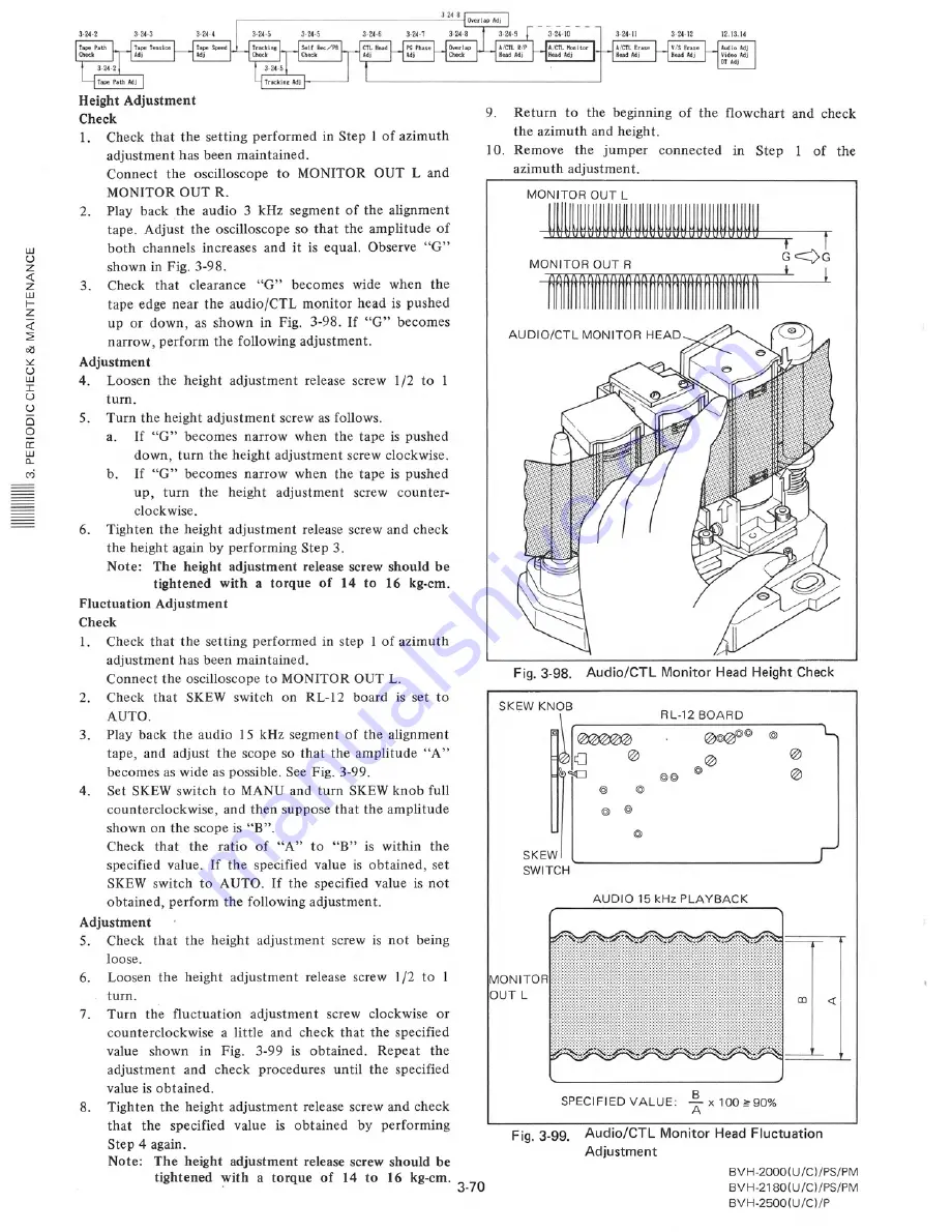
2.
Play back
the
audio
3
segment
of the alignment
tape.
Adjust
the oscilloscope
so that
the amplitude
of
both
channels
increases
and it is equal.
Observe
"G"
shown in Fig. 3-98.
3.
Check
that
clearance
"G"
becomes
wide
when
the
tape edge near the audio/C'TL
monitor
head is pushed
up or down,
as shown
in Fig.
3-98. If "G"
becomes
narrow,
perform
the following
adjustment.
Loosen
the height
release
screw
/2 to
turn.
5.
Turn the height
adjustment
screw as follows.
a.
If "G"
becomes
narrow
when
the tape is pushed
down,
turn the height
adjustment
screw clockwise.
b.
If "G"
becomes
narrow
when
the tape is pushed
up,
turn
the
height
adjustment
screw
counter-
clockwise.
6.
Tighten
the height
adjustment
release
screw and check
the height
again by performing
Step 3.
acnustment
release
of
Fluctuation
1\
rll111H:'li"1n'""O ....
1lt-
Check
1.
Check
that
the setting
performed
in step
I of azimuth
adjustment
has been maintained.
Connect
the oscilloscope
to MONITOR
OUT L.
2.
Check
that
SKEW
switch
on
RL-12
board
is set to
AUTO.
3.
Play back the audio
I 5
segmen t of the alignment
tape,
and adjust
the scope
so that
the amplitude
"A"
becomes
as wide as possible.
See Fig. 3-99.
4.
Set SKEW switch
to MANU and turn
SKEW knob full
counterclockwise,
and then suppose
that the amplitude
shown
on the scope is "B".
Check
that
the
ratio
of
"A"
to
"B"
is within
the
specified
value.
If the
specified
value
is obtained,
set
SKEW switch
to AUTO.
If the
specified
value
is not
obtained,
perform
the following
adjustment.
5.
Check
that
the height
adjustment
screw
is not
being
loose.
Loosen
the
height
adjustment
release
screw
I /2 to
1
turn.
Turn
the
fluctuation
adjustment
screw
clockwise
or
counterclockwise
a little
and check
that
the specified
value
shown
in
Fig.
3-99
is obtained.
Repeat
the
adjustment
and
check
procedures
until
the
specified
value is obtained.
Tighten
the
that
the
Step 4 again.
Note:
6.
7.
8.
adjustment
release
screw and check
value
is obtained
by
performing
acrustment
release
screw should
be
of
14
kg-em.
3-70
9.
Return
to
the beginning
of the
flowchart
and
check
the azimuth
and height.
O.
Remove
the
jumper
connected
in
Step
1 of
the
azimuth
adjustment.
MONITOR
OUT L
~'------
t
.---"J
G--vG
+
+
MONITOR
OUT R
~
AUDIO/CTL
MONITOR
HEAD
c-:
II
Fig. 3-98.
Audio/CTL
Monitor
Head Height Check
SKI;W KNOB
RL-12 BOARD
@@
@
@
@
@
SKEW
SWITCH
AUDIO
15 kHz PLAYBACK
MONITOR
OUT L
SPECIFIED
VALUE:
~
x
100 ;>;90%
Fig. 3-99.
Audio/CTL
Monitor
Head Fluctuation
BV H-2000 (U /C) IPS/PM
BVH-2180(U/C)/PS/PM
BVH-2500(U/C)/P
Содержание BVH-2000
Страница 1: ...he handles available panels are optional Iy ...
Страница 4: ......
Страница 11: ......
Страница 43: ......
Страница 45: ......
Страница 46: ......
Страница 73: ......
Страница 87: ......
Страница 91: ......
Страница 92: ......
Страница 103: ...2 ASSEMBLE or INSERT 1 AUTO MODE 6 ENTRY OUT 4 PLAY or SHUTTLE Editing point search 11 REVIEW 1 95 ...
Страница 105: ......
Страница 106: ......
Страница 114: ......
Страница 117: ......
Страница 118: ......
Страница 119: ......
Страница 120: ......
Страница 121: ......
Страница 122: ......
Страница 123: ......
Страница 124: ......
Страница 139: ......
Страница 141: ......
Страница 149: ......
Страница 150: ......
Страница 155: ......
Страница 161: ......
Страница 163: ......
Страница 179: ......
Страница 181: ...ARM 1 C C C ilr l I ...
Страница 185: ......
Страница 191: ......
Страница 195: ......
Страница 201: ......
Страница 203: ......
Страница 219: ......
Страница 221: ......
Страница 223: ......
Страница 224: ......
Страница 225: ......
Страница 226: ......
Страница 227: ......
Страница 228: ......
Страница 229: ......
Страница 239: ......
Страница 245: ......
Страница 250: ...z o i a o LL Z BVH 2000 U C PS PM BVH 2180 U C PS PM ...
Страница 257: ......
Страница 259: ......
Страница 265: ......
Страница 269: ......
Страница 305: ......
Страница 323: ......
Страница 344: ......
Страница 370: ...15 ...
Страница 371: ......
Страница 375: ......
Страница 388: ...of Standard Load for Output Check POWER UNIT 1 Standard for Variable a w o a 0 ...
Страница 396: ...CN921 8 1 Spec CN921 8 5 Spec hoard BVH 2000 U C PS PM BVH 2500 U C P on ON 100 OFF 5 ...
Страница 401: ......
Страница 435: ......
Страница 449: ......
Страница 452: ......
Страница 462: ......
Страница 471: ......
Страница 476: ......
Страница 480: ......
Страница 482: ... o w o ...
Страница 484: ......
Страница 492: ......
Страница 494: ...80 U C ...
Страница 496: ......
Страница 497: ......
Страница 498: ...14 2 BVH 2000 U C PS PM BVH 2500 U C P 80 U C PS PM w l j j Capstan Ree Servo Check ...
Страница 500: ...lel pin 3 12 0 01 Vdc RVl TP5 EQ 02 NG Edge Can nectar Pin 21 B A B R138 w I U U ...
Страница 504: ......
Страница 505: ...BVH 2000 U C 3 673 996 22 Volume 1 1985 Printed in Japan 1985 4 09 ...


