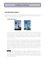
11. INSTALLING TEMPERATURE PROBES
11.1 Soil Temperature Probes
These probes are supplied ready to be inserted into the ground. The sensing
element is located 2cm from the tip of the probe, so this needs to be sited at
the depth at which you wish to measure the soil temperature.
If the ground sample to be monitored is soft, simply push the probe into the
surface to the required measurement depth. If the ground is harder or stony, it
may be necessary for a small hole to be made before inserting the probe.
Plug and screw up (do not overtighten) the temperature sensor connector into
the DataHog or MiniMet logger socket marked TEMPERATURE. Run the cable down the pole and /
or the guy ropes, securing with plastic cables to prevent movement and cable rubbing.
11.2 Grass Temperature Probes
These utilise the same element as 11.1 but the sensing element is not covered
- it is left exposed for a faster response. The wire from the element is
connected to the standard sensor cable, terminating in a plug, which is
screwed into the DataHog socket labelled TEMPERATURE.
These sensors can either be 'pegged' down on the grass, or mounted inside
our radiation screen which has been specially designed for grass
temperature measurements (SKRS 090). The purpose of mounting the
sensors inside a screen is to minimise the effect of direct sun heating up the sensing element.
1. Screw two threaded pillars into each aluminium skid plate so that the ends are flush with
the underside of the skid plate.
2. Place one long and one short white nylon spacer over each pillar.
3. Site the dish with the four sets of parallel holes and sticky pads over the pillars.
4. Ensure that the sticky pads are facing DOWN towards the skid plates
5. Place another long white nylon spacer over each pillar.
24
MiniMet Installation
Содержание MiniMet
Страница 1: ...MiniMet Installation Manual Iss 2 0...
Страница 45: ...APPENDIX 2 CONCRETE BASE FOR A 2M MAST 44 MiniMet Installation...
Страница 46: ...APPENDIX 3 SITE LOCATION 45 MiniMet Installation...
Страница 47: ...APPENDIX 4 ASSEMBLY OF MAST SUPPLIED IN MORE THAN ONE SECTION 46 MiniMet Installation...
Страница 49: ...APPENDIX 6 RAINGAUGE BASEPLATE 48 MiniMet Installation...
Страница 50: ...APPENDIX 7 MOUNTING OF GSM GPRS ENCLOSURE TO BRACKET 49 MiniMet Installation...
Страница 51: ...APPENDIX 8 MOUNTING THE GSM GPRS MODULE ON THE MAST NO SOLAR PANEL 50 MiniMet Installation...
Страница 52: ...APPENDIX 9 MOUNTING OF THE GSM GPRS UNIT ON THE MAST WITH A SOLAR PANEL STEP 1 51 MiniMet Installation...
Страница 53: ...APPENDIX 10 MOUNTING OF THE GSM GPRS UNIT ON THE MAST WITH A SOLAR PANEL STEP 2 52 MiniMet Installation...
Страница 54: ...APPENDIX 11 MOUNTING OF GSM GPRS UNIT ON THE MAST WITH A SOLAR PANEL STEP 3 53 MiniMet Installation...
Страница 55: ...APPENDIX 12 TYPICAL MINIMET INSTALLATION WITH GSM GPRS 54 MiniMet Installation...
Страница 56: ...APPENDIX 13 TYPICAL MINIMET INSTALLATION WITHOUT GSM GPRS 55 MiniMet Installation...
Страница 57: ...APPENDIX 14 56 MiniMet Installation...
Страница 58: ...APPENDIX 15 FITTING THE BATTERY COVER 57 MiniMet Installation...


