


17. FINAL SYSTEM ASSEMBLY
This chapter simply summarises the entire system assembly, but as each installation will be slightly different
and incorporate different combinations of sensors, it is only meant as a general overview.
Firstly, the mast should be erected as described in Chapter 3. Secondly, attach the GSM/GPRS unit if one
has been purchased. Then attach sensors and components starting from the bottom and finishing with the
highest.
Generally, wind sensors need to be at the highest point of the mast, and light sensors require a clear view
of the sunward sky, so these sensors require most consideration of their placing on the mast. Other sensors
are less critical in their placing.
17.1 Standard MiniMet Assembly
Appendix 13 shows a typical MiniMet weather station installation, with the standard Solar Hog
option. The raingauge is ground mounted and the soil temperature inserted into the soil. The Solar
Hog is usually mounted about halfway up the pole, facing towards the sun. A barometer can be
mounted next highest, its orientation is not critical.
The light or solar radiation sensor on its long arm pole mount can now be mounted so that the top
of the sensor is approximately at the height of the top of the pole, and orientated North or South as
appropriate.
The DataHog or MiniMet incorporating the RH and air temperature probes are usually placed
opposite the light sensor, to counter each other's weight. The short arm pole mount on the logger
means that it is possible to place the top of the radiation screen also at the height of the top of the
pole.
If the RH and air temperature sensors are separate from the datalogger, mount this on its long arm
bracket lower than the light sensor, to ensure that it does not obscure any sunlight from the sensor.
Finally, the wind sensor(s) are placed over the top of the pole using the pole cap mount.
Run cables up and down the pole as necessary, using gaps between the pole and the 'U' bolts,
cable ties and the supplied adhesive cable tidy to secure cables.
17.2 GSM/GPRS MiniMet Assembly
Appendix 12 shows a diagram of a typical GSM or GPRS assembly.
33
MiniMet Installation
Содержание MiniMet
Страница 1: ...MiniMet Installation Manual Iss 2 0...
Страница 45: ...APPENDIX 2 CONCRETE BASE FOR A 2M MAST 44 MiniMet Installation...
Страница 46: ...APPENDIX 3 SITE LOCATION 45 MiniMet Installation...
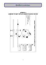
Страница 47: ...APPENDIX 4 ASSEMBLY OF MAST SUPPLIED IN MORE THAN ONE SECTION 46 MiniMet Installation...
Страница 49: ...APPENDIX 6 RAINGAUGE BASEPLATE 48 MiniMet Installation...
Страница 50: ...APPENDIX 7 MOUNTING OF GSM GPRS ENCLOSURE TO BRACKET 49 MiniMet Installation...
Страница 51: ...APPENDIX 8 MOUNTING THE GSM GPRS MODULE ON THE MAST NO SOLAR PANEL 50 MiniMet Installation...
Страница 52: ...APPENDIX 9 MOUNTING OF THE GSM GPRS UNIT ON THE MAST WITH A SOLAR PANEL STEP 1 51 MiniMet Installation...
Страница 53: ...APPENDIX 10 MOUNTING OF THE GSM GPRS UNIT ON THE MAST WITH A SOLAR PANEL STEP 2 52 MiniMet Installation...
Страница 54: ...APPENDIX 11 MOUNTING OF GSM GPRS UNIT ON THE MAST WITH A SOLAR PANEL STEP 3 53 MiniMet Installation...
Страница 55: ...APPENDIX 12 TYPICAL MINIMET INSTALLATION WITH GSM GPRS 54 MiniMet Installation...
Страница 56: ...APPENDIX 13 TYPICAL MINIMET INSTALLATION WITHOUT GSM GPRS 55 MiniMet Installation...
Страница 57: ...APPENDIX 14 56 MiniMet Installation...
Страница 58: ...APPENDIX 15 FITTING THE BATTERY COVER 57 MiniMet Installation...