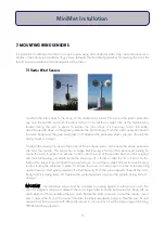
instrument arm. The ‘V’ channels should be facing away from instrument.
3. Place the two ‘U’ bolts through the bracket. The ‘U’ should mate with the ‘V’ on the bracket.
4. Place one washer then one M6 nut on each thread.
5. Next place one white spacer over each thread.
6. The adapter plate is next placed over the threads taking care that the box faces outermost with
the wires coming out of the bottom of the box.
7. Lastly, place one washer, one M6 nut and one end cap over the ends of each thread.
8. The complete assembly can now be slid over the top of the mast.
9. IMPORTANT. The instrument body has an ‘N’ printed on the side. Using a compass, align the ‘N’ so
that it is pointing NORTH.
10. When the sensor is in this position, it will be measuring wind coming FROM a northerly direction.
11. The M6 nuts can now be tightened to secure the assembly to the mast.
12. Plug and screw up (do not overtighten) the sensors connectors into the DataHog or MiniMet
logger sockets marked WIND SPEED and WIND DIRECTION respectively.
13. Use plastic cable ties to prevent cable movement and damage from rubbing.
7.3 Windsonic Wind Sensor
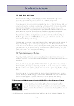
1. As this assembly is best sited as high up the mast as
possible, without causing interference to any of the
other instruments, it is easier to assemble the instrument
and bracket first and then slide it over the top of the
mast and secure.
2. Plug and screw up (do not overtighten) the cable to
the bottom of the instrument.
3. Slide the adapter collar over the cable and up to the base of the instrument, being careful to
align the three Allen screws in the instrument case with the three holes in the collar.
4. Tighten each Allen screw just enough to hold the collar in place.
5. Pass the cable through the supplied short section of tube.
17
MiniMet Installation
Содержание MiniMet
Страница 1: ...MiniMet Installation Manual Iss 2 0...
Страница 45: ...APPENDIX 2 CONCRETE BASE FOR A 2M MAST 44 MiniMet Installation...
Страница 46: ...APPENDIX 3 SITE LOCATION 45 MiniMet Installation...
Страница 47: ...APPENDIX 4 ASSEMBLY OF MAST SUPPLIED IN MORE THAN ONE SECTION 46 MiniMet Installation...
Страница 49: ...APPENDIX 6 RAINGAUGE BASEPLATE 48 MiniMet Installation...
Страница 50: ...APPENDIX 7 MOUNTING OF GSM GPRS ENCLOSURE TO BRACKET 49 MiniMet Installation...
Страница 51: ...APPENDIX 8 MOUNTING THE GSM GPRS MODULE ON THE MAST NO SOLAR PANEL 50 MiniMet Installation...
Страница 52: ...APPENDIX 9 MOUNTING OF THE GSM GPRS UNIT ON THE MAST WITH A SOLAR PANEL STEP 1 51 MiniMet Installation...
Страница 53: ...APPENDIX 10 MOUNTING OF THE GSM GPRS UNIT ON THE MAST WITH A SOLAR PANEL STEP 2 52 MiniMet Installation...
Страница 54: ...APPENDIX 11 MOUNTING OF GSM GPRS UNIT ON THE MAST WITH A SOLAR PANEL STEP 3 53 MiniMet Installation...
Страница 55: ...APPENDIX 12 TYPICAL MINIMET INSTALLATION WITH GSM GPRS 54 MiniMet Installation...
Страница 56: ...APPENDIX 13 TYPICAL MINIMET INSTALLATION WITHOUT GSM GPRS 55 MiniMet Installation...
Страница 57: ...APPENDIX 14 56 MiniMet Installation...
Страница 58: ...APPENDIX 15 FITTING THE BATTERY COVER 57 MiniMet Installation...


