7.1.1 Single Vector Wind Sensors
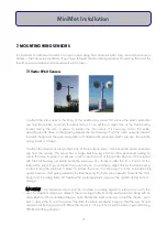
Wind sensors are usually placed at the highest point on the mast, although in some
applications there will be multiple wind sensors set at different height levels.
For a single sensor, for example one anemometer, the sensor is fitted to the mast pole top
using a mast cap. This aluminium cup type cap will fit over and fix to a pole of maximum
diameter 38 mm. Simply screw the wind sensor to the mast cap using the screw on the
underside of the sensor, fitting the large black spacing washer between the sensor and the
fixture. Place over the top of the mast and secure in place using the two locking bolts.
Plug and screw up (do not overtighten) the anemometer connector into the DataHog or
MiniMet logger socket marked WIND SPEED and use plastic cable ties to prevent cable
movement and damage from rubbng.
If multiple wind sensors are to mounted singly at different heights, each can be fitted to a
long arm bracket by using the same screw and spacer washer on the underside of the
sensor. Then mount the bracket on the pole at the required height by means of the 'U' bolts
provided. These can be fitted to masts up to 50 mm maximum diameter. Always use plastic
cable ties to prevent cable movement and rubbing.
7.1.2 Vector Anemometer plus Windvane
The white painted aluminium dual arm wind arm bracket is designed to mount two wind
sensors at the top of the mast pole of maximum diameter 38 mm, with minimal disturbance to
each other.
Screw one wind sensor to each end of the dual wind arm using the screw on the underside of
the sensor, fitting the large black spacing washer between the sensor and the wind arm.
Place the central cap over the top of the mast and secure in place using the two locking
bolts.
Plug and screw up (do not overtighten) the anemometer and windvane sensor connectors
into the DataHog or MiniMet logger socket marked WIND DIRECTION and use the white
plastic cable ties supplied to prevent cable movement and damage from rubbing.
7.2 Environmental Measurements Combined Wind Speed and Direction Sensors
1. As this assembly is best sited as high up the mast as possible, without
causing interference to any of the other instruments, it is easier to assemble
the instrument and bracket first and then slide it over the top of the mast and
secure.
2. Using two M6 bolts and washers, affix the larger plate with the two ‘V’ shaped channels to the
16
MiniMet Installation
Содержание MiniMet
Страница 1: ...MiniMet Installation Manual Iss 2 0...
Страница 45: ...APPENDIX 2 CONCRETE BASE FOR A 2M MAST 44 MiniMet Installation...
Страница 46: ...APPENDIX 3 SITE LOCATION 45 MiniMet Installation...
Страница 47: ...APPENDIX 4 ASSEMBLY OF MAST SUPPLIED IN MORE THAN ONE SECTION 46 MiniMet Installation...
Страница 49: ...APPENDIX 6 RAINGAUGE BASEPLATE 48 MiniMet Installation...
Страница 50: ...APPENDIX 7 MOUNTING OF GSM GPRS ENCLOSURE TO BRACKET 49 MiniMet Installation...
Страница 51: ...APPENDIX 8 MOUNTING THE GSM GPRS MODULE ON THE MAST NO SOLAR PANEL 50 MiniMet Installation...
Страница 52: ...APPENDIX 9 MOUNTING OF THE GSM GPRS UNIT ON THE MAST WITH A SOLAR PANEL STEP 1 51 MiniMet Installation...
Страница 53: ...APPENDIX 10 MOUNTING OF THE GSM GPRS UNIT ON THE MAST WITH A SOLAR PANEL STEP 2 52 MiniMet Installation...
Страница 54: ...APPENDIX 11 MOUNTING OF GSM GPRS UNIT ON THE MAST WITH A SOLAR PANEL STEP 3 53 MiniMet Installation...
Страница 55: ...APPENDIX 12 TYPICAL MINIMET INSTALLATION WITH GSM GPRS 54 MiniMet Installation...
Страница 56: ...APPENDIX 13 TYPICAL MINIMET INSTALLATION WITHOUT GSM GPRS 55 MiniMet Installation...
Страница 57: ...APPENDIX 14 56 MiniMet Installation...
Страница 58: ...APPENDIX 15 FITTING THE BATTERY COVER 57 MiniMet Installation...


