14. MOUNTING THE SOLAR HOG POWER SUPPLY
This chapter describes the mounting of the Solar Hog power supply for
DataHog and MiniMets dataloggers. To mount the solar power source
for the GSM/GPRS remote link options, please see Section 16.
The Solar Hog optional solar power source contains its own
rechargeable batteries which can permanently power the DataHog or
MiniMet system. A bracket is incorporated in the Solar Hog's design
which has four mounting holes on its back plate, suitable for bolting to a
wall or vertical surface. It is supplied as standard with a pair of 'V' bolts,
washers, nuts and end caps used for fixing to a pole or mast up to a
maximum diameter of 50 mm. See Appendix 5.
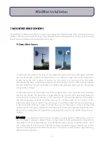
The Solar Hog requires a fairly clear view of the sun and sky in order to
be able to charge its batteries. Hence it should be mounted in a
southerly direction in the Northern Hemisphere, or a northerly direction
in the Southern Hemisphere. However, if the DataHog or MiniMet system also contains a light or solar
radiation sensor, this sensor must take priority over positional placing, and must not be obscured. It is
acceptable for the Solar Hog to be shaded for a short time during the day, as the sun passes overhead
and above the light sensor, but preferably this shouldn't happen when the sun is highest, around midday.
So the Solar Hog should not be installed directly underneath the light sensor, but at about 45 degrees to
the side, so that it receives strong early morning or strong late afternoon sunshine, which is usually sufficient to
keep all batteries charged.
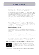
Plug and screw up (do not overtighten) the Solar Hog 8 pin connector into the DataHog or MiniMet logger
socket marked RS232 and use plastic cable ties to prevent cable movement and damage from chafing.
The RS232 socket is used for connecting the logger to the PC. There is a secondary RS232 socket on the
Solar Hog which must now be used for the computer connection, so that the solar power supply to the
logger is not interrupted.
28
MiniMet Installation
Содержание MiniMet
Страница 1: ...MiniMet Installation Manual Iss 2 0...
Страница 45: ...APPENDIX 2 CONCRETE BASE FOR A 2M MAST 44 MiniMet Installation...
Страница 46: ...APPENDIX 3 SITE LOCATION 45 MiniMet Installation...
Страница 47: ...APPENDIX 4 ASSEMBLY OF MAST SUPPLIED IN MORE THAN ONE SECTION 46 MiniMet Installation...
Страница 49: ...APPENDIX 6 RAINGAUGE BASEPLATE 48 MiniMet Installation...
Страница 50: ...APPENDIX 7 MOUNTING OF GSM GPRS ENCLOSURE TO BRACKET 49 MiniMet Installation...
Страница 51: ...APPENDIX 8 MOUNTING THE GSM GPRS MODULE ON THE MAST NO SOLAR PANEL 50 MiniMet Installation...
Страница 52: ...APPENDIX 9 MOUNTING OF THE GSM GPRS UNIT ON THE MAST WITH A SOLAR PANEL STEP 1 51 MiniMet Installation...
Страница 53: ...APPENDIX 10 MOUNTING OF THE GSM GPRS UNIT ON THE MAST WITH A SOLAR PANEL STEP 2 52 MiniMet Installation...
Страница 54: ...APPENDIX 11 MOUNTING OF GSM GPRS UNIT ON THE MAST WITH A SOLAR PANEL STEP 3 53 MiniMet Installation...
Страница 55: ...APPENDIX 12 TYPICAL MINIMET INSTALLATION WITH GSM GPRS 54 MiniMet Installation...
Страница 56: ...APPENDIX 13 TYPICAL MINIMET INSTALLATION WITHOUT GSM GPRS 55 MiniMet Installation...
Страница 57: ...APPENDIX 14 56 MiniMet Installation...
Страница 58: ...APPENDIX 15 FITTING THE BATTERY COVER 57 MiniMet Installation...


