6. LEVELLING UNITS FOR LIGHT SENSORS
The aluminium levelling unit holds any of the Skye light and radiation sensors
securely in place and can be levelled to ensure that the top of the sensor is
mounted horizontally. This is essential for accurate and repeatable
measurements, as the sensors have a 180 degree hemispherical light
acceptance area, the lower horizon of which must be level to ensure only
incident light is received and to prevent reflection from the ground also being
measured.
There are two styles of levelling unit. One where the light sensor is placed in a
central holder with its cable passing through the provided opening, and
secured with the 2 nylon screws. The levelling unit can then be attached to a
pole / wall mount, or be sat on any flat surface to facilitate levelling using the
three nylon bolts with locking wing nuts, and the level bubble. The other
levelling unit does not have the central holder. Instead the sensor is fixed to a
flat levelling unit with an M6 screw from underneath.
There are 2 more nylon bolts supplied for fixing to either a long or short arm
mounting bracket. The brackets have four mounting holes on the flat back plate,
suitable for bolting to a wall or vertical surface. They are supplied as standard
with a pair of 'V' bolts, washers, nuts and end caps used for fixing to a pole or
mast up to a maximum diameter of 50 mm. See Appendix 5 for assembly of
mounting brackets.
Plug and screw up (do not over-tighten) the light sensor connector into the
DataHog or MiniMet logger socket marked LIGHT and use plastic cable ties to
prevent cable movement and damage from rubbing.
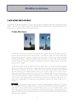
Light sensors should be mounted in a fully open area, so that no shadow or
shade will fall across its surface at any time of day or at any sun angle. In
general, mount facing directly southwards in the northern hemisphere, or directly
northwards in the southern hemisphere, to ensure that the sensor is always pointing towards the direction of
the sun.
For accurate measurements it is important to ensure that the levelling unit is level. As this sensor is usually
mounted quite high up on the mast, use a mirror to view the level bubble on the unit and adjust accordingly.
14
MiniMet Installation
Содержание MiniMet
Страница 1: ...MiniMet Installation Manual Iss 2 0...
Страница 45: ...APPENDIX 2 CONCRETE BASE FOR A 2M MAST 44 MiniMet Installation...
Страница 46: ...APPENDIX 3 SITE LOCATION 45 MiniMet Installation...
Страница 47: ...APPENDIX 4 ASSEMBLY OF MAST SUPPLIED IN MORE THAN ONE SECTION 46 MiniMet Installation...
Страница 49: ...APPENDIX 6 RAINGAUGE BASEPLATE 48 MiniMet Installation...
Страница 50: ...APPENDIX 7 MOUNTING OF GSM GPRS ENCLOSURE TO BRACKET 49 MiniMet Installation...
Страница 51: ...APPENDIX 8 MOUNTING THE GSM GPRS MODULE ON THE MAST NO SOLAR PANEL 50 MiniMet Installation...
Страница 52: ...APPENDIX 9 MOUNTING OF THE GSM GPRS UNIT ON THE MAST WITH A SOLAR PANEL STEP 1 51 MiniMet Installation...
Страница 53: ...APPENDIX 10 MOUNTING OF THE GSM GPRS UNIT ON THE MAST WITH A SOLAR PANEL STEP 2 52 MiniMet Installation...
Страница 54: ...APPENDIX 11 MOUNTING OF GSM GPRS UNIT ON THE MAST WITH A SOLAR PANEL STEP 3 53 MiniMet Installation...
Страница 55: ...APPENDIX 12 TYPICAL MINIMET INSTALLATION WITH GSM GPRS 54 MiniMet Installation...
Страница 56: ...APPENDIX 13 TYPICAL MINIMET INSTALLATION WITHOUT GSM GPRS 55 MiniMet Installation...
Страница 57: ...APPENDIX 14 56 MiniMet Installation...
Страница 58: ...APPENDIX 15 FITTING THE BATTERY COVER 57 MiniMet Installation...


