Sitex SP38 Installation and Operation
Document PN
29010101
V2r0
- 5
8
-
Operating Modes and Menus Continued
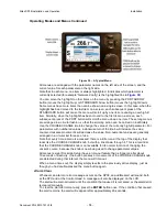
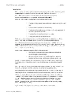
Figure 30 – A Typical Menu
All menus are arranged with the parameter names on the left side of the screen, and the
current value for each parameter on the right side.
Note that in each menu, one item is always highlighted, it indicates which parameter is
currently selected (for example “Network Config” is the highlighted line in
Figure 30
).
You can move the highlight to other items on the menu by pressing the PORT ARROW
button (moves the highlight up) or STARBOARD Arrow button (moves the highlight down).
Some menus have more items than can be shown on a single screen. In this case, when the
highlight has been moved to the last item on a screen, each subsequent press of the
STARBOARD button will cause the menu will scroll up by one item, revealing a new high-lit
item. Similarly, when the highlight has been moved to the first item on a screen, each
subsequent press of the PORT button will scroll the menu down one item. These long menus
are arranged in a circular fashion, so that the scrolling action can be carried on indefinitely.
Use the COURSE CHANGE knob to change the value of the currently high-lit parameter. For
parameters with numbered values, a clockwise turn of the knob will increase the value;
counter-clockwise movements will decrease the value. Non-numerical values are generally
arranged in a circular list for ease of use.
Note that every time a menu is accessed, there is a little icon at the top of the display that
looks like the COURSE CHANGE knob, but with a line drawn through it. This is a reminder
that the COURSE CHANGE knob is not available for its normal function of changing the
vessel’s course, because the knob is now being used to change parameter values.
All menus (except Dockside Setup) have a time-out feature that is triggered after about
10 seconds of inactivity. If no button presses or movements of the COURSE CHANGE knob
are detected during that interval, the menu will time-out.
When a menu times out, the display simply reverts to the previously active display, just as
though you had double-pressed the menu button again.
Alarm Clear
Whenever an alarm or error message occurs on the
SP38
, an audible alert will sound, both
at the SPU and at the Control Head. A message will also be displayed on the LCD.
The alert will remain activated until the condition that caused it is remedied, or the alarm/error
is cleared manually.
To clear the alarm/error manually, press the
ENTER
button once. If the condition that caused
the alert remains, the alert will reappear after approximately 20 seconds.
Installation
Содержание SP38 Autopilot
Страница 2: ......
Страница 14: ...Sitex SP38 Installation and Operation Document PN 29010101 V2r0 13 ...
Страница 15: ...Sitex SP38 Installation and Operation Document PN 29010101 V2r0 14 Introduction ...
Страница 16: ...Sitex SP38 Installation and Operation Document PN 29010101 V2r0 15 ...
Страница 25: ...System Overview Sitex SP38 Installation and Operation Document PN 29010101 V2r0 24 System Overview ...
Страница 26: ...Sitex SP38 Installation and Operation Document PN 29010101 V2r0 25 ...
Страница 35: ...Sitex SP38 Installation and Operation Document PN 29010101 V2r0 34 Installation ...
Страница 36: ...Sitex SP38 Installation and Operation Document PN 29010101 V2r0 35 ...
Страница 73: ...Sitex SP38 Installation and Operation Basic Operation Document PN 29010101 V2r0 72 Basic Operations ...
Страница 74: ...Sitex SP38 Installation and Operation Document PN 29010101 V2r0 73 ...
Страница 108: ...Sitex SP38 Installation and Operation Document PN 29010101 V2r0 107 ...
Страница 109: ...Sitex SP38 Installation and Operation Document PN 29010101 V2r0 108 Advanced Operations ...
Страница 110: ...Sitex SP38 Installation and Operation Document PN 29010101 V2r0 109 ...
Страница 123: ...Sitex SP38 Installation and Operation Document PN 29010101 V2r0 122 Care and Maintenance ...
Страница 124: ...Sitex SP38 Installation and Operation Document PN 29010101 V2r0 123 ...
Страница 127: ...Sitex SP38 Installation and Operation Document PN 29010101 V2r0 126 Appendices ...
Страница 128: ...Sitex SP38 Installation and Operation Document PN 29010101 V2r0 127 ...
Страница 156: ...Sitex SP38 Installation and Operation Document PN 29010101 V2r0 155 Warranty ...
Страница 157: ...Sitex SP38 Installation and Operation Document PN 29010101 V2r0 156 User Notes and Settings ...
Страница 158: ...Sitex SP38 Installation and Operation Document PN 29010101 V2r0 157 ...
Страница 162: ...Sitex SP38 Installation and Operation User Notes and Settings Document PN 29010101 V2r0 161 User Notes ...

