Sitex SP38 Installation and Operation
Table of Contents, Lists of Figures and Tables
Document PN
29010101
V2r0
-
10
-
List of Figures
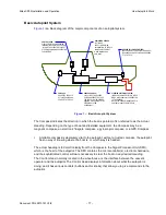
Figure 1 – Basic Autopilot System .................................................................................................................. 17
Figure 2 – Heading Change in AUTO Mode ................................................................................................... 20
Figure 3 –
SP38
System Block Diagram ........................................................................................................ 26
Figure 4 – Control Head .................................................................................................................................. 27
Figure 5 – The
SP38
SPU with Wiring and Diagnostic Covers Removed ...................................................... 28
Figure 6 – G2 GPS Compass ......................................................................................................................... 29
Figure 7 – Rotary Rudder Follower ................................................................................................................. 30
Figure 8 – Rudder Follower Linkage Geometry .............................................................................................. 31
Figure 9 – Heavy Duty Rotary Rudder Follower ............................................................................................. 32
Figure 10a – SPU Plug Wiring Details ............................................................................................................ 39
Figure 10b – SPU Connector Details .............................................................................................................. 40
Figure 11 – Typical Battery Connection to SPU ............................................................................................. 41
Figure 12 – Reducing Supply Voltage Losses ................................................................................................ 42
Figure 13 – Wiring Connections for
SP38
SPU to N2000 Networks .............................................................. 42
Figure 14 – Wiring Connections for Rudder Followers ................................................................................... 43
Figure 15 – Wiring Connections for Reversing DC Motors ............................................................................. 43
Figure 16 – Wiring Connections for Linear Actuators or Mechanical Rotary Drives ....................................... 44
Figure 17 – Wiring Connections for Shunt Field Reversing Motors ................................................................ 44
Figure 18 – Wiring Connections for Standard Four-Way Solenoid Valves ..................................................... 45
Figure 19 – Wiring Connections for Constant Running Electric Pump ........................................................... 45
Figure 20 – Wiring Connections for A.C. Solenoids ....................................................................................... 46
Figure 21 – External Alarm, using SW'D B- Output ........................................................................................ 46
Figure 22 – External Alarm, using SW'D B+ Output ....................................................................................... 47
Figure 23 – External Alarm, SW'D B- Output – with Power Fail Option .......................................................... 47
Figure 24 – External Alarm, SW'D B+ Output – with Power Fail Option ......................................................... 48
Figure 25 – Thruster Signals for SPU-T .......................................................................................................... 50
Figure 26 –
SP38
Control Head – Rear View ................................................................................................. 51
Figure 27 – Battery Connection to Master
SP38
Head ..................................................................................
52
Figure 28 – Introductory Display ..................................................................................................................... 55
Figure 29 – Using the Control Head ............................................................................................................... 55
Figure 30 – A Typical Menu ............................................................................................................................ 58
Figure 31 – Autopilot in Standby Mode ........................................................................................................... 59
Figure 32 – Data Sources used by
SP38
Autopilot .........................................................................................
5
9
Figure 33 – Set Vessel Type ........................................................................................................................... 64
Figure 34 – Set Compass Type in Compass Configuration Menu .................................................................. 67
Figure 35 – System Menu Tree ...................................................................................................................... 74
Figure 36 – System Menu Screenshot ........................................................................................................... 74
Figure 37 – Network Configure Menu ............................................................................................................. 78
Figure 38 – Dockside Menu Enter from System Menu ................................................................................... 81
Figure 39 –
SP38
System Setup .................................................................................................................... 82
Figure 40 – Standby Menu ............................................................................................................................. 86
Figure 41 – Typical Power Steer Mode Screen .............................................................................................. 89
Figure 42 – Power Steer Menu ....................................................................................................................... 89
Figure 43 – Typical Auto Mode Screen .......................................................................................................... 91
Figure 44 – Typical Auto Menu Screen .......................................................................................................... 92
Figure 45 – Guidelines for setting Counter Rudder ........................................................................................ 93
Figure 46 – HI and LO Speed Icons (Left of Rudder Angle Indicator) ............................................................ 94
Figure 47 – Typical NAV Mode Screen (Normal Display) ............................................................................... 95
Содержание SP38 Autopilot
Страница 2: ......
Страница 14: ...Sitex SP38 Installation and Operation Document PN 29010101 V2r0 13 ...
Страница 15: ...Sitex SP38 Installation and Operation Document PN 29010101 V2r0 14 Introduction ...
Страница 16: ...Sitex SP38 Installation and Operation Document PN 29010101 V2r0 15 ...
Страница 25: ...System Overview Sitex SP38 Installation and Operation Document PN 29010101 V2r0 24 System Overview ...
Страница 26: ...Sitex SP38 Installation and Operation Document PN 29010101 V2r0 25 ...
Страница 35: ...Sitex SP38 Installation and Operation Document PN 29010101 V2r0 34 Installation ...
Страница 36: ...Sitex SP38 Installation and Operation Document PN 29010101 V2r0 35 ...
Страница 73: ...Sitex SP38 Installation and Operation Basic Operation Document PN 29010101 V2r0 72 Basic Operations ...
Страница 74: ...Sitex SP38 Installation and Operation Document PN 29010101 V2r0 73 ...
Страница 108: ...Sitex SP38 Installation and Operation Document PN 29010101 V2r0 107 ...
Страница 109: ...Sitex SP38 Installation and Operation Document PN 29010101 V2r0 108 Advanced Operations ...
Страница 110: ...Sitex SP38 Installation and Operation Document PN 29010101 V2r0 109 ...
Страница 123: ...Sitex SP38 Installation and Operation Document PN 29010101 V2r0 122 Care and Maintenance ...
Страница 124: ...Sitex SP38 Installation and Operation Document PN 29010101 V2r0 123 ...
Страница 127: ...Sitex SP38 Installation and Operation Document PN 29010101 V2r0 126 Appendices ...
Страница 128: ...Sitex SP38 Installation and Operation Document PN 29010101 V2r0 127 ...
Страница 156: ...Sitex SP38 Installation and Operation Document PN 29010101 V2r0 155 Warranty ...
Страница 157: ...Sitex SP38 Installation and Operation Document PN 29010101 V2r0 156 User Notes and Settings ...
Страница 158: ...Sitex SP38 Installation and Operation Document PN 29010101 V2r0 157 ...
Страница 162: ...Sitex SP38 Installation and Operation User Notes and Settings Document PN 29010101 V2r0 161 User Notes ...


