Sitex SP38 Installation and Operation
Document PN
29010101
V2r0
-
52
-
Wiring the Control Head
The
SP38
Control Head operates in the same voltage range as the
SP38
SPU. See
3.2.2 Wire Gauge Requirements
(see Table 1)
for details.
Caution! The
SP38
Head are NOT reverse-polarity protected.
If you wire the wrong voltage polarity at J1, you will damage
the SPU and Control Head! This will void the warranty.
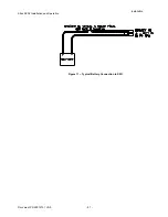
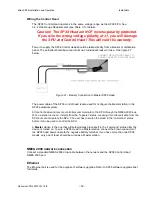
Power to supply the
SP38
Control Head should be taken directly from a breaker or distribution
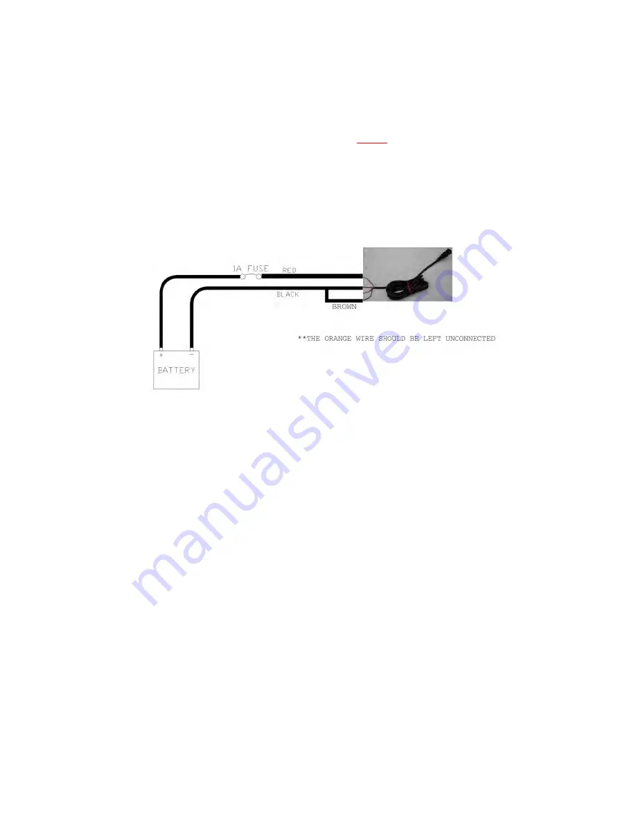
panel. The autopilot should be wired into its own individual breaker or fuse. See figure 27
below.
Figure.27 – Battery Connection to Master
SP38
Head
The power cable of the
SP38
control head is also used for configure the Master station in the
SP38
autopilot system.
All control heads and remote controllers communicate to the SPU through the NMEA 2000 bus.
When a station turns on, it starts from the “repeater” status, meaning it monitors all data from the
SPU but cannot operate the SPU. The user has to switch the Head to the “command” status
before it can be used to control the SPU.
A
Master
station is the one that will automatically place itself to the “command” status after the
device is turned on. To wire a
SP38
Head to a Master station, connect the brown conductor of
the
SP38
head power cable to the negative battery terminal. If you have more than one
SP38
Heads, only one of them should be wired as a Master station.
NMEA 2000 network connection
Connect a standard NMEA 2000 drop cable between the network and the
SP38
Control Head
NMEA 2000 port.
Ethernet
The Ethernet port is used for the purpose of software upgrade. Refer to
SP38
software upgrade brief
for details.
Installation
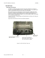
CONNECT HEAD POWER CABLE TO
POWER CONNECTOR OF SP38 HEAD
Содержание SP38 Autopilot
Страница 2: ......
Страница 14: ...Sitex SP38 Installation and Operation Document PN 29010101 V2r0 13 ...
Страница 15: ...Sitex SP38 Installation and Operation Document PN 29010101 V2r0 14 Introduction ...
Страница 16: ...Sitex SP38 Installation and Operation Document PN 29010101 V2r0 15 ...
Страница 25: ...System Overview Sitex SP38 Installation and Operation Document PN 29010101 V2r0 24 System Overview ...
Страница 26: ...Sitex SP38 Installation and Operation Document PN 29010101 V2r0 25 ...
Страница 35: ...Sitex SP38 Installation and Operation Document PN 29010101 V2r0 34 Installation ...
Страница 36: ...Sitex SP38 Installation and Operation Document PN 29010101 V2r0 35 ...
Страница 73: ...Sitex SP38 Installation and Operation Basic Operation Document PN 29010101 V2r0 72 Basic Operations ...
Страница 74: ...Sitex SP38 Installation and Operation Document PN 29010101 V2r0 73 ...
Страница 108: ...Sitex SP38 Installation and Operation Document PN 29010101 V2r0 107 ...
Страница 109: ...Sitex SP38 Installation and Operation Document PN 29010101 V2r0 108 Advanced Operations ...
Страница 110: ...Sitex SP38 Installation and Operation Document PN 29010101 V2r0 109 ...
Страница 123: ...Sitex SP38 Installation and Operation Document PN 29010101 V2r0 122 Care and Maintenance ...
Страница 124: ...Sitex SP38 Installation and Operation Document PN 29010101 V2r0 123 ...
Страница 127: ...Sitex SP38 Installation and Operation Document PN 29010101 V2r0 126 Appendices ...
Страница 128: ...Sitex SP38 Installation and Operation Document PN 29010101 V2r0 127 ...
Страница 156: ...Sitex SP38 Installation and Operation Document PN 29010101 V2r0 155 Warranty ...
Страница 157: ...Sitex SP38 Installation and Operation Document PN 29010101 V2r0 156 User Notes and Settings ...
Страница 158: ...Sitex SP38 Installation and Operation Document PN 29010101 V2r0 157 ...
Страница 162: ...Sitex SP38 Installation and Operation User Notes and Settings Document PN 29010101 V2r0 161 User Notes ...

