Sitex SP38 Installation and Operation
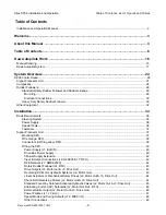
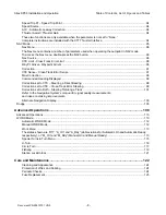
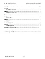
Table of Contents, Lists of Figures and Tables
Document PN
29010101
V2r0
-
11
-
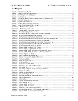
Figure 50 – Steering with Correction set to XTE .......................................................................................... 100
Figure 51 – Response of Vessel to a Large Cross-Track Error .................................................................... 101
Figure 52 – Steering with Correction set to Both .......................................................................................... 102
Figure 53 – Typical NAV Mode Screen (Alternate Display) .......................................................................... 103
Figure 54 – A Dodge in Progress (in AUTO Mode) ...................................................................................... 104
Figure 55 – Vessel Track During a Dodge Manoeuvre in AUTO Mode ........................................................ 104
Figure 56 – Typical Jog Lever Activated Screen .......................................................................................... 105
Figure 57 – Typical WORK Mode Screen (Engaged) ................................................................................... 111
Figure 58 – Work Mode Menu ...................................................................................................................... 113
Figure 59 – Typical Special Turn Query ....................................................................................................... 115
Figure 60 – U-Turn Query ............................................................................................................................. 116
Figure 61 – U-Turn Vessel Path .................................................................................................................. 116
Figure 62 – Circle Turn Query ...................................................................................................................... 117
Figure 63 – Circle Turn Vessel Path ............................................................................................................. 117
Figure 64 – M.O.B. Turn Query .................................................................................................................... 118
Figure 65 – M.O.B. Turn Vessel Path ........................................................................................................... 118
Figure 66 – Fishzag Turn Query ................................................................................................................... 119
Figure 67 – Fishzag Turn .............................................................................................................................. 119
Figure 68 – Turn Menu Screen ..................................................................................................................... 120
Figure 69 – Station Lock Icons on the screen .............................................................................................. 121
Figure 70 – NMEA 0183 / NMEA 2000 system ............................................................................................ 128
Figure 71 – GNSS G2 GPS Compass .......................................................................................................... 129
Figure 72 – Typical NMEA 0183 Connections .............................................................................................. 129
Figure 73 – Fluxgate Compass ..................................................................................................................... 131
Figure 74 – Wiring Connections for Analog Compasses .............................................................................. 131
Figure 75 – Externally Gimballed Magnetic Compass with Magnetic Sensor .............................................. 132
Figure 76 – CR-203 Handheld Remote ........................................................................................................ 134
Figure 77 – TS-203 Fixed Remote ................................................................................................................ 135
Figure 78 – Wiring Connections for Control Head, Handheld and Fixed Remotes ...................................... 136
Figure 79 – Jog Lever ................................................................................................................................... 137
Figure 80 – Wiring Connections for Jog Levers ............................................................................................ 137
Figure 81 – External Rudder Angle Indicator – 3” Model .............................................................................. 139
Figure 82 – Wiring Connections for rudder Angle Indicators ........................................................................ 139
Figure 48 – Nav Menu .................................................................................................................................... 96
Figure 49 – Steering with Correction set to CTS ............................................................................................ 98
Содержание SP38 Autopilot
Страница 2: ......
Страница 14: ...Sitex SP38 Installation and Operation Document PN 29010101 V2r0 13 ...
Страница 15: ...Sitex SP38 Installation and Operation Document PN 29010101 V2r0 14 Introduction ...
Страница 16: ...Sitex SP38 Installation and Operation Document PN 29010101 V2r0 15 ...
Страница 25: ...System Overview Sitex SP38 Installation and Operation Document PN 29010101 V2r0 24 System Overview ...
Страница 26: ...Sitex SP38 Installation and Operation Document PN 29010101 V2r0 25 ...
Страница 35: ...Sitex SP38 Installation and Operation Document PN 29010101 V2r0 34 Installation ...
Страница 36: ...Sitex SP38 Installation and Operation Document PN 29010101 V2r0 35 ...
Страница 73: ...Sitex SP38 Installation and Operation Basic Operation Document PN 29010101 V2r0 72 Basic Operations ...
Страница 74: ...Sitex SP38 Installation and Operation Document PN 29010101 V2r0 73 ...
Страница 108: ...Sitex SP38 Installation and Operation Document PN 29010101 V2r0 107 ...
Страница 109: ...Sitex SP38 Installation and Operation Document PN 29010101 V2r0 108 Advanced Operations ...
Страница 110: ...Sitex SP38 Installation and Operation Document PN 29010101 V2r0 109 ...
Страница 123: ...Sitex SP38 Installation and Operation Document PN 29010101 V2r0 122 Care and Maintenance ...
Страница 124: ...Sitex SP38 Installation and Operation Document PN 29010101 V2r0 123 ...
Страница 127: ...Sitex SP38 Installation and Operation Document PN 29010101 V2r0 126 Appendices ...
Страница 128: ...Sitex SP38 Installation and Operation Document PN 29010101 V2r0 127 ...
Страница 156: ...Sitex SP38 Installation and Operation Document PN 29010101 V2r0 155 Warranty ...
Страница 157: ...Sitex SP38 Installation and Operation Document PN 29010101 V2r0 156 User Notes and Settings ...
Страница 158: ...Sitex SP38 Installation and Operation Document PN 29010101 V2r0 157 ...
Страница 162: ...Sitex SP38 Installation and Operation User Notes and Settings Document PN 29010101 V2r0 161 User Notes ...


