62 14 972 D 3507
D 3507
.
031.01.07
.
02 11.2010
47
Sirona Dental Systems GmbH
Electrical connection
Installation Instructions HELIODENT
PLUS
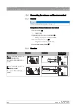
Connecting the release and the door contact
båÖäáëÜ
empty
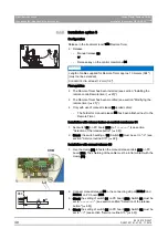
Installation of cable L9 (on DX1)
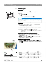
1. Connect cable L9 to connectors X401.1 and X401.4 on PC board
DX1.
2. Secure cable L9 with the shielding clamp (B).
empty
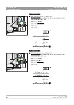
Installation with remote control release button S9
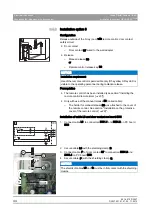
➢ Connect cable L9, release button S9, and the door contact cable to
the 3-pin terminal as shown.
● Cable drawn in black = concealed installation
● Cable drawn in gray = surface installation
1. Connect the shield of cable L9 to the shield of door contact D
underneath the strain relief clamp (T).
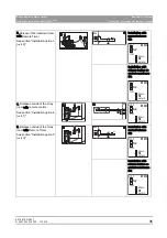
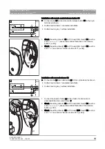
2. Check the setting of switch S1 on PC board DX4. Switch S1 must be
set to "
external
". (see section entitled "Selection of the release
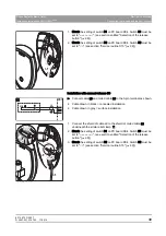
3. Check the setting of switch S2 on PC board DX4. Switch S2 must be
set to "
ON
“ (see section "Service routine S15 [ ➙ 69]").
L9
6.1
X401.1
X401.2
X401.3
X401.4
DX1
S3/S9
S7
X401
B
L9
NOTICE
The shielding of cable L9 must be in flat contact with the shielding clamp
(B).
L9
6.1
X401.1
X401.2
X401.3
X401.4
DX1
S3/S9
S7
D
T
Содержание Heliodent plus
Страница 1: ...NNKOMNM ebiflabkqmirp k W b f f HELIODENT PLUS 7mA DC 7mA DC 70kV 60kV S 008...
Страница 2: ......


