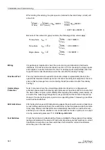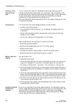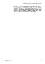
3 Installation and Commissioning
354
7UM62 Manual
C53000-G1176-C149-3
After the completion of the test, check that all provisional measures for testing have
been reversed:
−
Earthing bridge or resistor has been removed,
−
Measurement circuit has been closed,
−
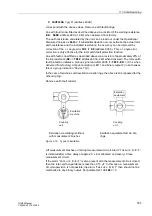
Controller unit connected to its operational supply a.c. voltage (refer also
connection diagram in Figure 2-95 in Section 2.25.1).
Tests with the running machine are described later under section 3.4.9.
3.3.7.2
Rotor Earth Fault Protection (1 to 3 Hz)
The rotor earth fault protection can be checked with the machine at stand-still. For this
purpose, the series device 7XT71 must be supplied with an external AC voltage of
100 V to 125 V AC (see also to connection diagram Figure A-36 in the Appendix).
Switch the rotor earth fault protection (address
) to Block relay.
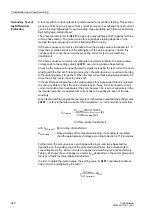
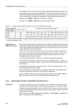
In fault-free condition, the following operational measured values are read out from the
protection device and evaluated (see Table 3-24).The operational measured values
can be found in the earth fault measured values (in DIGSI see tab “earth fault mea-
sured values”).
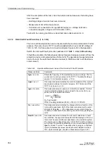
Table 3-24
Operational Measured Values of the Rotor Earth Fault Protection
Measured Value
Comments
fgen = xx.x Hz
Shows the frequency of the injected square-wave voltage. The fre-
quency can be set by a jumper in the 7XT71. The default setting is
approx. 1.5 Hz (tolerance approx. ± 10 %).
Ugen = xx.x V
This measured value indicates the current amplitude of the injected
square-wave voltage. It amounts to approx. 50 V (tolerance of the
7XT71 can be up to ± 4 V).
Igen = X.xx mA
This measured value is nearly zero in fault-free condition. If a fault
resistor is installed between rotor and earth, the current to be ex-
pected can be estimated as follows:
R
E
: Fault resistor
Rtotal: Coupling resistance (20 k
Ω
+ 720
Ω
= 20.720 k
Ω
)
Qc = x.xxx mAs
This measured value indicates the charge which is a function of the
rotor earth capacitance. Half of the measured value must be set at
address
as
. If the capacitance is very small, it may be
necessary to deactivate the measuring circuit monitoring (setting val-
ue 0).
Rearth = xxx.x k
Ω
This measured value indicates the rotor earth resistance. In fault-
free condition, the upper limit value 999.9 k
Ω
is displayed. If it is not,
there must be some additional capacitance in the excitation system.
The square-wave voltage frequency in the 7XT71 must be reduced
by a jumper. No polarity reversal may occur in the measuring current
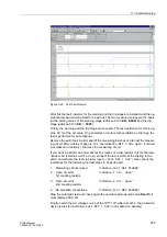
Igen for at least 3 cycles. To visualize what is going on, a test fault
record (instantaneous values record) should be started and track
TD2, which models Igen, should be checked (see Figure 3-20).
Igen
Ugen
R
E
Rtotal
+
-------------------------------
≈

