


Measured Value Monitoring Functions
249
7UM62 Manual
C53000-G1176-C149-3
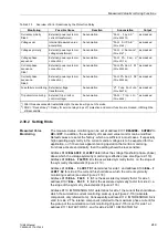
2.38.2 Setting Hints
Measured Value
Monitoring
The measured value monitoring can be set at address
to
ON
or
OFF
. In addition, the sensitivity of measured value monitor can be modified.
Default values are set at the factory, which are sufficient in most cases. If especially
high operating asymmetry in the currents and/or voltages is to be expected for the
application, or if it becomes apparent during operation that certain monitoring
Functions activate sporadically, then the setting should be less sensitive.
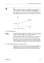
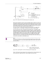
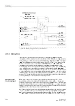
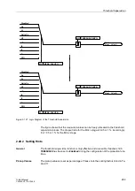
Address
determines the voltage threshold (phase–phase)
above which the voltage symmetry monitoring is effective (see also Figure 2-119).
Address
is the associated symmetry factor, i.e. the slope of
the symmetry characteristic (Figure 2-119).
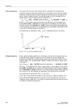
Address
determines for side 1, and address
for side 2, the current threshold above which the current symmetry
monitoring is active (see also Figure 2-118).
Address
is the associated symmetry factor for side 1,
address
is the associated symmetry factor for side 2, i.e.
the slope of the symmetry characteristic (Figure 2-118).
Address
I THRESHOLD S1 determines for side 1 the current threshold above
which the summation current monitoring picks up (see Figure 2-116) (absolute
component, only referred to I
N
). Consequently, address
valid for side 2. The relative component (referred to the maximum phase current) for
the pickup of the summation current monitoring (Figure 2-116) is set for side 1 at
address
I FACTOR S1, and for side 2 at
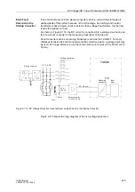
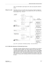
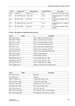
Current symmetry
Side 2
External (power system or
current transformer)
Annunciation
”
(FNo. 000572)
as masked
Voltage sum
Internal (measured value
acquisition)
Annunciation
”
(FNo. 0165)
as masked
Voltage symmetry
External (power system or
voltage transformer)
Annunciation
”
”
(FNo. 0167)
as masked
Voltage phase
sequence
External (power system or
connection)
Annunciation
”
”
(FNo. 00176)
as masked
Current phase
sequence
Side 1
External (power system or
connection)
Annunciation
”
”
(FNo. 000265)
as masked
Current phase
sequence
Side 2
External (power system or
connection)
Annunciation
”
”
(FNo. 000266)
as masked
Fuse failure monitoring External (voltage
transformers)
Annunciation
”
”
(FNo. 06575)
as masked
Trip circuit monitoring
External (trip circuit or
control voltage)
Annunciation
”
”
(FNo. 6865)
as masked
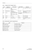
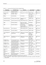
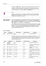
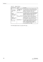
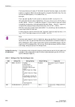
Table 2-13
Overview of Error Reactions by the Protection Relay
Monitoring
Possible Cause
Reaction
Annunciation
Output
1
) After three unsuccessful restart attempts, the device will go out of service
2
) DOK = ”Device Okay” = Ready for service relay drops off, protection and control function are blocked, HMI might be
still accessible


