3.1 Installation and Connections
335
7UM62 Manual
C53000-G1176-C149-3
Analog Output
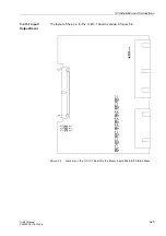
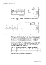
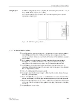
The AN20 analog output board (see Figure 3-15) has 2 floating channels with a current
range of 0 to 20 mA (unipolar, max. 350
Ω
).
The location on the C–CPU–2 board is “B” or/and “D” depending on the variant
ordered (see Figure 3-12).
Figure 3-15
AN20 Analog Output Board
3.1.3.5
To Reassemble the Device:
o
Carefully insert the boards into the case. The installation locations of the boards are
shown in Figures 3-5 and 3-6. For the model of the device designed for surface-
mounting, use the metal lever to insert the C–CPU–2 board. The installation is easier
with the lever.
o
By first attaching to the I/O board(s), connect the ribbon cable between the I/O
board(s) and the C–CPU–2 board. Be especially careful not to bend any of the
connector pins! Do not use any force! Be sure that the plug connectors latch.
o
Connect the ribbon cable between the C–CPU–2 board and the front cover. Be
especially careful not to bend any of the connector pins! Do not use any force! Be sure
that the plug connectors latch.
o
Close the locking clips of the plug connectors.
o
Carefully replace the front cover being mindful of the ribbon-cable. Fasten the cover
to the case with the screws.
o
Insert and tighten the screw-posts for the D-subminiature connector at location “A” on
the rear of the device. This activity does not apply if the device is for surface mounting.
o
Insert and tighten the screws for the communication interfaces at locations “B” and “C”
on the back panel of the device. This activity does not apply if the device is for surface
mounting.
o
Replace the four corner covers.

