


Mounting and Commissioning
3.1 Mounting and Connections
SIPROTEC, 7SJ62/64, Manual
C53000-G1140-C207-2, Release date 01.2008
428
RS232 Interface
Interface RS232 can be modified to interface RS485 and vice versa (see Figures 3-20 and 3-21).
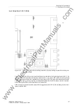
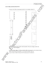
Figure 3-19 shows the printed circuit board C–CPU and the interface modules.
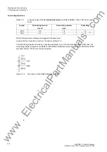
The following figure shows the location of the jumpers of interface RS232 on the interface module.
Devices in surface mounting housing with fiber optics connection have their fiber optics module housed in the
console housing. The fiber optics module is controlled via a RS232 interface module at the associated CPU
interface slot. For this application type the jumpers X12 and X13 on the RS232 module are plugged in position
2-3.
Figure 3-20
Location of the jumpers for configuration of RS232
Terminating resistors are not required. They are permanently disconnected.
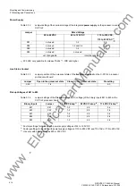
Jumper X11 enables the
flow control (CTS)
feature which is important for modem communication.
Table 3-30
Jumper setting for
CTS (Clear to Send)
on the interface module
1)
Default setting
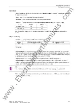
Jumper setting 2-3:
. The modem connection is usually established with star coupler or fiber optic converter.
Therefore the modem control signals according to RS232 Standard DIN 66020 are not available. The modem
signals are not required since the connection to the SIPROTEC 4 devices is always operated in the half-duplex
mode. Please use the connection cable with order number 7XV5100-4.
Jumper setting 2-3 is equally required when using the RTD boxes in half-duplex operation.
Jumper setting 1-2
: This setting makes the modem signals available, i.e. for a direct RS232 connection
between the SIPROTEC 4 device and the modem this setting can be selected optionally. We recommend to
use a standard RS232 modem connection cable (converter 9-pin to 25-pin).
Note
For a direct connection to DIGSI with interface RS232, jumper X11 must be plugged in position 2-3.
Jumper
/CTS from interface RS232
/CTS controlled by /RTS
X11
1-2
2-3
www
. ElectricalPartManuals
. com


