


Functions
2.14 Automatic Reclosing System 79
SIPROTEC, 7SJ62/64, Manual
C53000-G1140-C207-2, Release date 01.2008
258
2.14.4
Controlling Protection Elements
Depending on the reclosing cycle it is possible to control elements of the directional and non-directional over-
current protection by means of the automatic reclosure system (Protective Elements Control). There are three
mechanisms:
1.
Time overcurrent elements may trip instantaneously depending on the automatic reclosure cycle (T = 0),
they may remain unaffected by the auto reclosing function AR (T = T) or may be blocked (T =
∞
). For further
information see side title "Cyclic Control".
2.
The automatic reclosing states "Auto Reclosing ready" and "Auto Reclosing not ready" can activate or de-
activate the dynamic cold load pickup function. This function is designed to influence overcurrent stages
(see also Section 2.14.6 and Section 2.4) regarding thresholds and tripping time delays.
3.
The time overcurrent protection parameter 1X14A 50(N)-2 ACTIVE or 1X16A 50(N)-3 ACTIVE defines
whether the elements 50(N)-2 or 50(N)-3 are to operate always or only with "79M Auto Reclosing
ready"(see Section 2.2).
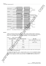
Cyclic Control
Control of the time overcurrent protection elements takes effect by releasing the cycle marked by the corre-
sponding parameter. The cycle zone release is indicated by the messages
„79 1.CycZoneRel“
to
„79
4.CycZoneRel“
. If the automatic reclosure system is in normal state, the settings for the starting cycle apply.
These settings always take effect when the automatic reclosure system assumes normal state.
The settings are released for each following cycle when issuing the close command and starting the blocking
time. Following a successful reclosure (blocking time expired) or after returning from the blocking, the auto-
reclose function goes into normal state. Control of the protection is again assumed by the parameters for the
starting cycle.
The following figure illustrates the control of the protection elements 50-2 and 50N-2.
www
. ElectricalPartManuals
. com


