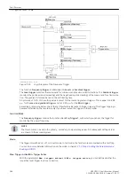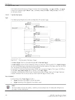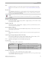
Mode
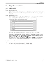
The trigger is switched on, off, or in test mode. In test mode, the fault records are marked with a test flag.
You can find more detailed information on the mode in chapter
7.1.3 Step 2: Setting the Parameters and
.
Switching on Trigger Max./Trigger Min.
With the parameters
Max. trigger active
and
Min. trigger active
, you define whether the respec-
tive level trigger is active or inactive.
Trigger Max./Trigger Min.
With the parameters
Max. trigger
and
Min. trigger
, you define from which threshold value the acti-
vated level trigger starts a fault record.
Switch on dM/dt Rise - dM/dt Drop
With the parameters
dM/dt rise active
and
dM/dt drop active
, you define whether the respective
gradient trigger is active or inactive.
Filter Time
With the
Filter time
parameter, you define the number of periods with which the gradient is determined.
Gradient Trigger for Rising and Dropping Gradients of the Active, Reactive, and Apparent Power
With the parameters
dM/dt rise (/Filter time)
and
dM/dt drop (/Filter time)
, you define
from which threshold value within the set filtering time a fault record is started.
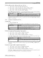
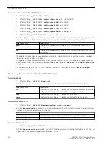
Application and Setting Notes – Trigger P
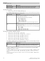
Parameter: Mode
•
Default setting
(_:19411:1) Mode
=
off
With the
Mode
parameter, you activate the trigger for normal operation (On) or the test mode (Test).
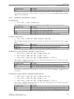
Parameter Value
Description
on
The Trigger P function block is activated and the sum active power is moni-
tored according to the set trigger parameters.
off
The Trigger P function block is deactivated.
test
The Trigger P function block is activated for test purposes.
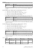
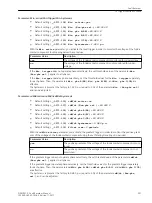
Parameter: Power Direction
•
Default setting
(_:19411:111) Power direction
=
positive
With the
Power direction
parameter, you can trigger on negative powers if the parameter is set to
nega-
tive
.
Parameter Value
Description
positive
This setting value has no influence on the trigger thresholds.
negative
This setting value multiplies the trigger threshold by -1.
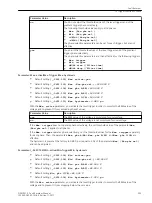
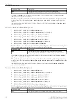
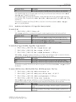
Parameter: Max. Trigger Active/Max. Trigger/Max. Trigger Hysteresis
•
Default setting
(_:19411:101) Max. trigger active
=
yes
•
Default setting
(_:19411:105) Max. trigger
=
0 W
•
Default setting
(_:19411:113) Max. trigger hysteresis
=
0.980 p.u.
7.4.4.4
Fault Recorder
7.4 Trigger Functions 1-Phase
SIPROTEC 5, Fault Recorder, Manual
291
C53000-G5040-C018-5, Edition 11.2017
Содержание SIPROTEC 5
Страница 8: ...8 SIPROTEC 5 Fault Recorder Manual C53000 G5040 C018 5 Edition 11 2017 ...
Страница 18: ...18 SIPROTEC 5 Fault Recorder Manual C53000 G5040 C018 5 Edition 11 2017 ...
Страница 134: ...134 SIPROTEC 5 Fault Recorder Manual C53000 G5040 C018 5 Edition 11 2017 ...
Страница 212: ...212 SIPROTEC 5 Fault Recorder Manual C53000 G5040 C018 5 Edition 11 2017 ...
Страница 422: ...422 SIPROTEC 5 Fault Recorder Manual C53000 G5040 C018 5 Edition 11 2017 ...
Страница 426: ...426 SIPROTEC 5 Fault Recorder Manual C53000 G5040 C018 5 Edition 11 2017 ...
Страница 452: ...452 SIPROTEC 5 Fault Recorder Manual C53000 G5040 C018 5 Edition 11 2017 ...
Страница 490: ...490 SIPROTEC 5 Fault Recorder Manual C53000 G5040 C018 5 Edition 11 2017 ...

