[scauser6-190214-01, 1, en_US]
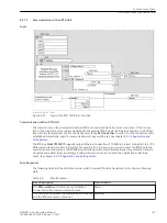
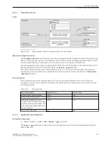
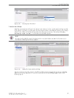
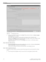
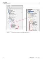
Figure 6-64
Analog-Unit Instance
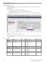
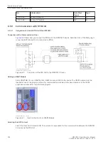
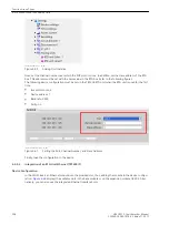
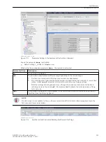
Now, set the channel number over which the SUP protocol runs. In addition, set the slave address of the RTD
box. This address must be set with the same value in the RTD box (refer to the following figure).
The following device configuration must be set on the TR1200 RTD unit when the RTD unit is used for the first
time:
•
Bus protocol: mod
•
Device address: 1
•
Baud rate: 9600
•
Parity: no
[scauser7-220114-01-DE, 1, en_US]
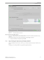
Figure 6-65
Setting the Port, Channel Number, and Slave Address
Finally, load the configuration in the device.
Integration of an RTD-Unit Ethernet (TR1200 IP)
Device Configuration
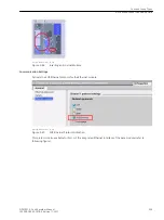
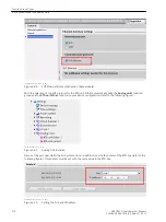
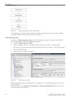
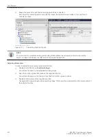
In the DIGSI, insert an Ethernet module into the provided slot, thus, adding the module to the device configu-
ration.
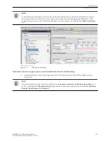
displays the available slots in the base module or on the expansion module CB 202. Alter-
natively, you can also use the integrated Ethernet interface Port J.
6.5.9.2
Function-Group Types
6.5 Function-Group Type Analog Units
208
SIPROTEC 5, Fault Recorder, Manual
C53000-G5040-C018-5, Edition 11.2017
Содержание SIPROTEC 5
Страница 8: ...8 SIPROTEC 5 Fault Recorder Manual C53000 G5040 C018 5 Edition 11 2017 ...
Страница 18: ...18 SIPROTEC 5 Fault Recorder Manual C53000 G5040 C018 5 Edition 11 2017 ...
Страница 134: ...134 SIPROTEC 5 Fault Recorder Manual C53000 G5040 C018 5 Edition 11 2017 ...
Страница 212: ...212 SIPROTEC 5 Fault Recorder Manual C53000 G5040 C018 5 Edition 11 2017 ...
Страница 422: ...422 SIPROTEC 5 Fault Recorder Manual C53000 G5040 C018 5 Edition 11 2017 ...
Страница 426: ...426 SIPROTEC 5 Fault Recorder Manual C53000 G5040 C018 5 Edition 11 2017 ...
Страница 452: ...452 SIPROTEC 5 Fault Recorder Manual C53000 G5040 C018 5 Edition 11 2017 ...
Страница 490: ...490 SIPROTEC 5 Fault Recorder Manual C53000 G5040 C018 5 Edition 11 2017 ...

