


Circuit diagrams
3VL molded-case circuit breakers
System Manual, 03/2009, 110 0110 - 02 DS 01
319
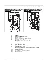
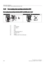
5RWDU\PHFKDQLVP
/HDGLQJ
$X[LOLDU\VZLWFKHV
(06
(%6
) )
&
'
&
'
8
.
+6
$6
)
4
7
7
7
7
7
.
/
1
.
/ .
/
.
/
7
1
$
,!
,!
/
6
,
HS
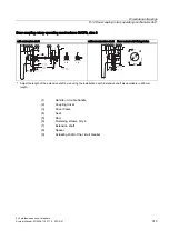
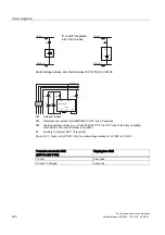
Auxiliary switches
AS
Alarm switches
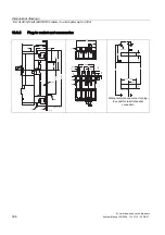
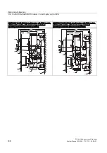
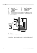
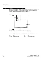
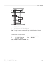
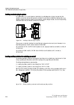
Figure 14-3 Internal circuit diagram for VL400 circuit breaker for motor protection, and VL400-
VL1600
3- and 4-pole circuit breakers for line protection with electronic trip units
Содержание SENTRON 3VL series
Страница 2: ......
Страница 10: ...Table of contents 3VL molded case circuit breakers 10 System Manual 03 2009 110 0110 02 DS 01 ...
Страница 40: ...System overview 4 2 Key data 3VL molded case circuit breakers 40 System Manual 03 2009 110 0110 02 DS 01 ...
Страница 350: ...Correction sheet 3VL molded case circuit breakers 350 System Manual 03 2009 110 0110 02 DS 01 ...
Страница 358: ...Glossary 3VL molded case circuit breakers 358 System Manual 03 2009 110 0110 02 DS 01 ...
Страница 359: ......


