


Parameter assignment/addressing
10.2 Setting the protection parameters for motor protection (ETU10M, ETU30M and LCD-ETU 40M)
3VL molded-case circuit breakers
System Manual, 03/2009, 110 0110 - 02 DS 01
139
10.2
Setting the protection parameters for motor protection (ETU10M,
ETU30M and LCD-ETU 40M)
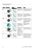
The selection of the circuit breaker is oriented around the rated operating current of the
motor; the releases are specially designed for overload protection of 3-phase motors.
Overload release I
R
:
The overload release I
R
is set to the rated current of the motor, similarly to protection
parameters for line and generator protection. The overload protection is finely adjustable with
the left rotary encoding switch (first decimal place) and the center rotary encoding switch
(second decimal place) in the range between I
R
= 0.41; 0.42 to 0.98; 0.99; 1 x I
n
(I
n
= rated
breaker current).
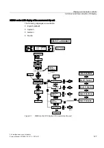
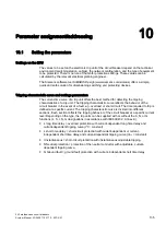
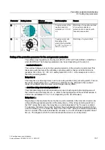
Example
Adjusting to the motor current 360 A is carried out for the rotary encoding switch left and
center (ETU10M and ETU30M) (rated breaker current I
n
= 500 A) as follows:
.5
.9
.8 .7
.4
.6
.4
.4 .4
.4
.07
.04
.06 .05
.08
.10
.09
.01
.03
.02
1.5
1.25
Alarm
Active
>1.05
X3
R
I
x
I
n
x
I
n
I
i
6
3
5
4
10
8
2
11
+
Overload protection setting
Setting I
R
/ rated breaker current I
n
= 360 A / 500 A = 0.72
1.
Setting the rotary encoding switch left factor 0.7
2.
Setting the rotary encoding switch center factor 0.02
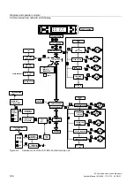
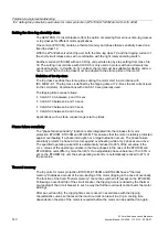
Short-circuit release I
i
Furthermore, instantaneous short-circuit release I
i
can also be set depending on the trip unit.
This setting value refers to the rated current I
n
of the circuit breaker. As with line and
generator protection, the minimum short-circuit must be taken into account when selecting
the setting.
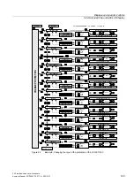
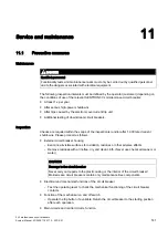
With the ETU30M version, you must note that the setting of the short-circuit release is
selected in combination with the time-lag class. The rotary encoding switch is divided into
three areas here, corresponding to the values 6, 8 or 11 x I
n
. The desired time-lag class can
be selected within these ranges.
.5
.9
.8 .7
.4
.6
.4
.4 .4
.4
.07
.04
.06 .05
.08
.10
.09
.01
.03
.02
Alarm
Active
>1.05
X3
R
I
x
I
n
+
I
i
I
i
I
n
I
n
I
i
I
n
20
10
=8x
=11x
10
30
20
20
Test
30
10
TC
30
=6x
Содержание SENTRON 3VL series
Страница 2: ......
Страница 10: ...Table of contents 3VL molded case circuit breakers 10 System Manual 03 2009 110 0110 02 DS 01 ...
Страница 40: ...System overview 4 2 Key data 3VL molded case circuit breakers 40 System Manual 03 2009 110 0110 02 DS 01 ...
Страница 350: ...Correction sheet 3VL molded case circuit breakers 350 System Manual 03 2009 110 0110 02 DS 01 ...
Страница 358: ...Glossary 3VL molded case circuit breakers 358 System Manual 03 2009 110 0110 02 DS 01 ...
Страница 359: ......


