


Connecting
8.5 Auxiliary switch designations
3VL molded-case circuit breakers
118
System Manual, 03/2009, 110 0110 - 02 DS 01
8.5
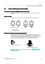
Auxiliary switch designations
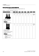
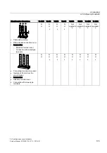
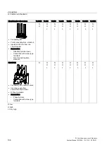
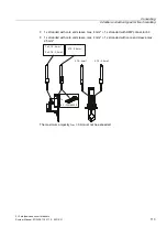
Connection designations for auxiliary switches (NC and NO)
If the circuit breakers are supplied from the factory with integral auxiliary switches, these are
designated in accordance with the operating instructions.
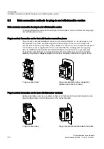
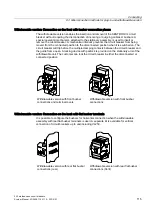
The compartments (cutouts) in each circuit breaker (behind the front cover) for installing
accessories are designated X1, X2 and X4. The terminals of the installed accessories are
numbered consecutively. The contacts remain as designated in the catalog.
The contact designations on the auxiliary (HS) and alarm switches (AS) are replaced by the
stickers supplied.
8.6
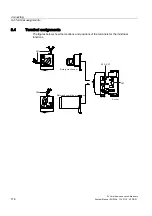
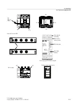
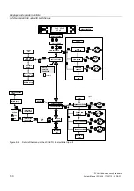
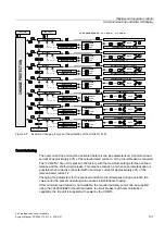
Description of the terminals
Description of the terminals
The exact positions and functions of the separate terminals are listed in this table for the
Description of the terminals.
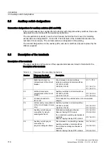
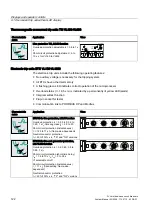
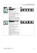
Table 8- 4
Overview of the secondary connections
Number
Where are the circuit
breakers/accessories?
Description
X1
Right-hand accessory
compartment of the circuit
breaker
Shunt release and undervoltage
release, auxiliary and alarm switches
VL160X to VL400
VL630 to VL1600
X1.1 + X1.2
X1.1 to X1.6
X1.1 to X1.8
X2
Left-hand accessory
compartment of the circuit
breaker
Auxiliary switches and alarm switches
VL160X to VL400
VL630 to VL1600
X2.1 to X2.6
X2.1 to X2.8
X3
Connection socket to
ETU LCD
I/O connection for portable tester or communication
adapter
X4
Left accessory compartment
of the circuit breaker (4-pole
only)
Auxiliary switches and alarm switches
VL160X to VL400
VL630 to VL1600
X4.1 to X4.6
X4.1 to X4.8
X5
Auxiliary current plug-in
connection for plug-in
socket/guide frame
Motorized operating mechanism
Remote tripping RCD module
If no motorized operating mechanism is
available:
Remote tripping display RCD module
X5.1 to X5.5
X5.6 to X5.8
X5.1 to X5.3
X6
Auxiliary current plug-in
connection for
plug-in socket/guide frame
Shunt release or undervoltage release
Auxiliary switches or alarm switches
If motorized operating mechanism is
available:
Remote tripping display RCD module
X6.1 to X6.2
X6.3 to X6.8
X6.6 to X6.8
Содержание SENTRON 3VL series
Страница 2: ......
Страница 10: ...Table of contents 3VL molded case circuit breakers 10 System Manual 03 2009 110 0110 02 DS 01 ...
Страница 40: ...System overview 4 2 Key data 3VL molded case circuit breakers 40 System Manual 03 2009 110 0110 02 DS 01 ...
Страница 350: ...Correction sheet 3VL molded case circuit breakers 350 System Manual 03 2009 110 0110 02 DS 01 ...
Страница 358: ...Glossary 3VL molded case circuit breakers 358 System Manual 03 2009 110 0110 02 DS 01 ...
Страница 359: ......


