


Circuit diagrams
3VL molded-case circuit breakers
318
System Manual, 03/2009, 110 0110 - 02 DS 01
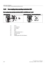
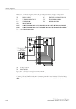
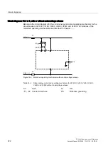
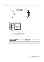
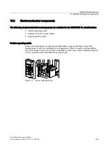
Table 14- 1 Terminal assignments for rotary operating mechanism, leading auxiliary switch
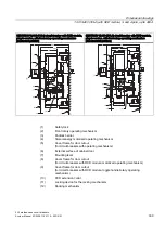
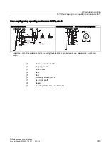
Q1
Main contacts
A1
Electronic overcurrent trip unit
F1
Tripping solenoid for A1
F2
Undervoltage release
F3
Shunt release
HS
Auxiliary switches
AS
Alarm switches
EBS
Leading auxiliary switch ON (integrated into the rotary operating mechanism)
EMS
Leading auxiliary switch OFF (integrated into the rotary operating mechanism)
T1 ... T4 Current transformer
5RWDU\PHFKDQLVP
/HDGLQJ
$X[LOLDU\VZLWFKHV
(06
(%6
) )
&
'
&
'
8
.
+6
$6
)
4
7
7
7
7
7
.
/
1
.
/ .
/
.
/
7
1
$
,!
,!
/
6
,
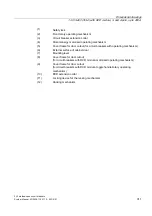
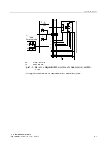
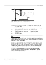
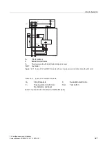
HS
Auxiliary switches
AS
Alarm switches
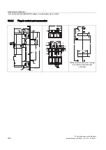
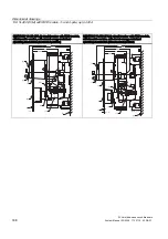
Figure 14-2 Internal circuit diagram for VL160-VL250
3- and 4-pole circuit breakers for line and motor protection with electronic overcurrent trip
units
Содержание SENTRON 3VL series
Страница 2: ......
Страница 10: ...Table of contents 3VL molded case circuit breakers 10 System Manual 03 2009 110 0110 02 DS 01 ...
Страница 40: ...System overview 4 2 Key data 3VL molded case circuit breakers 40 System Manual 03 2009 110 0110 02 DS 01 ...
Страница 350: ...Correction sheet 3VL molded case circuit breakers 350 System Manual 03 2009 110 0110 02 DS 01 ...
Страница 358: ...Glossary 3VL molded case circuit breakers 358 System Manual 03 2009 110 0110 02 DS 01 ...
Страница 359: ......


