


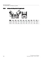


Dimensional drawings
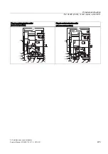
13.3 VL630 (3VL5), 3- and 4-pole, up to 630 A
3VL molded-case circuit breakers
System Manual, 03/2009, 110 0110 - 02 DS 01
229
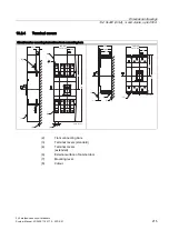
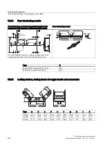
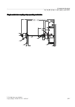
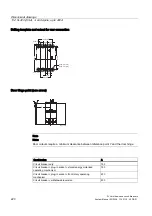
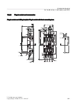
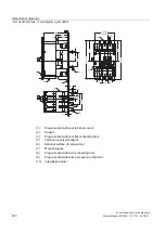
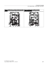
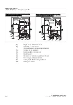
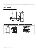
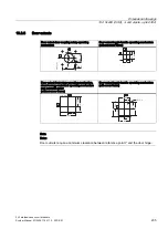
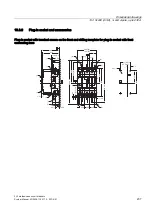
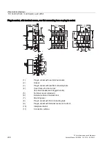
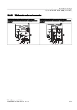
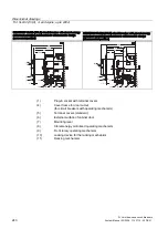
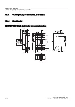
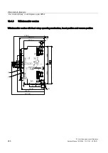
13.3.3
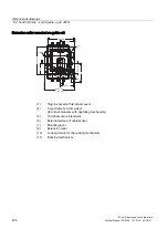
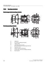
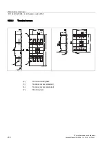
Connections and phase barriers
Z
( 1 )
( 2 )
( 7 )
X
( 2 )
Y
( 1 )
( 8 )
( 1 )
X
7 6
2 7 0 . 5 ( 4 P )
9 7 . 5
4
2
6
9 . 5
2
2
4
2 9
1 0 6 . 5
4
0
9
6 3 . 5 ( 4 P )
6 3 . 5
2 1
6 3 . 5
4 2
1
5
2
0
0
.5
3
7
9
2 5 . 5
1 9 4 . 5 ( 3 P )
9 7
2
1
5
.5
4
0
9
2
0
0
.5
X
Y
1 2 . 5
N S E 0 _ 0 1 1 8 4 b
1 2 . 5
3
7
9
Ø 1 1
( 3 )
( 7 )
X
Z
( 5 )
( 4 )
2 - 6
1 0 6 . 5
1 8
1 8
6 6 . 5
1 5
6 6 . 5
12
.5
13
0.
5
1 1 . 1
32
23
9.
5
N
S
E
0_
01
18
5
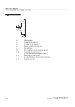
(1)
Interphase barrier
(2)
Front connecting bars
(3)
Terminal covers (standard)
(4)
Rear connection (horizontal connection)
(5)
Rear connection (vertical connection)
(7)
Mounting level
(8)
Flared busbar extensions
Содержание SENTRON 3VL series
Страница 2: ......
Страница 10: ...Table of contents 3VL molded case circuit breakers 10 System Manual 03 2009 110 0110 02 DS 01 ...
Страница 40: ...System overview 4 2 Key data 3VL molded case circuit breakers 40 System Manual 03 2009 110 0110 02 DS 01 ...
Страница 350: ...Correction sheet 3VL molded case circuit breakers 350 System Manual 03 2009 110 0110 02 DS 01 ...
Страница 358: ...Glossary 3VL molded case circuit breakers 358 System Manual 03 2009 110 0110 02 DS 01 ...
Страница 359: ......


