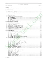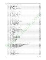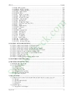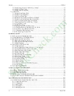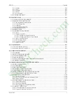
Contents
UM353-1
vi
March
2003
WARRANTY
SOFTWARE RELEASE MEMO
LIST OF ILLUSTRATIONS
FIGURE AND TITLE
PAGE
1-1 Moore 353, Exploded View............................................................................................................................ 1-2
1-2 Ethernet
Architecture Example....................................................................................................................... 1-4
2-1 Configuration Road Map ................................................................................................................................ 2-6
3-1 PCOM Logic Diagram.................................................................................................................................. 3-81
8-1 Direct Entry Connectors, Cover Installation and Removal............................................................................. 8-4
8-2 Side Entry Connectors, Removing a Connector ............................................................................................. 8-5
8-3 Panel
Cutout Dimensions................................................................................................................................ 8-5
8-4 Moore 353 Dimensions, Direct Entry Connectors.......................................................................................... 8-6
8-5 Moore 353 Dimensions, Side Entry Connectors............................................................................................. 8-6
8-6 Case
Mounting Clip ........................................................................................................................................ 8-7
8-7 Rear Terminal Layout and Terminal Assignments, Direct Entry Connectors .............................................. 8-10
8-8 Rear Terminal Layout and Terminal Assignments, Side Entry Connectors ................................................. 8-11
8-9 Analog Input AIN1, 2-Wire Transmitter ...................................................................................................... 8-13
8-10 Analog Inputs ANI1, 2, and 3; 4-Wire Transmitters .................................................................................... 8-14
8-11 Universal Analog Input AINU1.................................................................................................................... 8-14
8-12 Analog Output AOUT1, Current Output ...................................................................................................... 8-15
8-13 Analog Output AOUT1, Voltage Output...................................................................................................... 8-15
8-14 Digital Inputs DIN and DINU ...................................................................................................................... 8-16
8-15 Digital Output DOUT1, Resistive and Inductive Loads ............................................................................... 8-17
8-16 Universal Analog Input AINU1, Thermocouple Input ................................................................................. 8-18
8-17 Reference Junction Lead Forms.................................................................................................................... 8-18
8-18 Universal Analog Input AINU1; 2, 3, and 4-Wire RTD Inputs.................................................................... 8-19
8-19 Universal Analog Input AINU1, Ohms Input............................................................................................... 8-20
8-20 Universal Analog Input AINU1, Slidewire Input......................................................................................... 8-20
8-21 Universal Relay Outputs ROUT1 and 2, Resistive Load.............................................................................. 8-20
8-22 LIL Network Wiring..................................................................................................................................... 8-21
8-23 LonWorks Network Wiring.......................................................................................................................... 8-22
8-24 Modbus Communications, Personal Computer to Moore 353 or Moore 354............................................... 8-23
8-25 Moore 353 to Model 363 VIEWPAC Analog Input Wiring ........................................................................ 8-24
8-26 Controller Power Wiring .............................................................................................................................. 8-24
8-27 Suggested Power Wiring .............................................................................................................................. 8-25
8-28 Daisy Chained Power Wiring ....................................................................................................................... 8-25
11-1 Moore 353 Exploded View........................................................................................................................... 11-5
11-2 MPU Controller Board with RTC Jumper W8 ............................................................................................. 11-6
11-3 MPU Controller Board with RTC Jumper W7 ............................................................................................. 11-7
11-4 I/O Expander Board.................................................................................................................................... 11-15
11-5 Accessory Board Installation and Replacement.......................................................................................... 11-16
11-6 LIL Network Board .................................................................................................................................... 11-18
11-7 Ethernet
Board ............................................................................................................................................ 11-18
11-8 LonWorks
Board ........................................................................................................................................ 11-19
11-9 Real Time Clock/Configuration Backup Board.......................................................................................... 11-19
13-1 Moore 353 Block Diagram ........................................................................................................................... 13-1
StockCheck.com
Содержание Moore 353
Страница 2: ...S t o c k C h e c k c o m ...
Страница 14: ...Contents UM353 1 xii March 2003 S t o c k C h e c k c o m ...
Страница 24: ...Introduction UM353 1 March 2003 1 10 S t o c k C h e c k c o m ...
Страница 152: ...LonWorks Communications UM353 1 March 2003 5 4 S t o c k C h e c k c o m ...
Страница 164: ...Network Communications UM353 1 6 12 March 2003 S t o c k C h e c k c o m ...
Страница 246: ...Operation UM353 1 March 2003 9 8 S t o c k C h e c k c o m ...
Страница 254: ...Controller and System Test UM353 1 March 2003 10 8 S t o c k C h e c k c o m ...
Страница 282: ...Circuit Description UM353 1 March 2003 13 4 S t o c k C h e c k c o m ...
Страница 298: ...Model Designation and Specifications UM353 1 March 2003 14 16 S t o c k C h e c k c o m ...
Страница 302: ...Abbreviations And Acronyms UM353 1 15 2 March 2003 S t o c k C h e c k c o m ...
Страница 304: ...Warranty UM353 1 W 2 March 2003 S t o c k C h e c k c o m ...

