background image

UM353-1 

Maintenance 

March 2003 


11-5 

MPU CONTROLLER BOARD JUMPERS


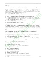
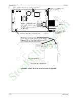
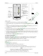
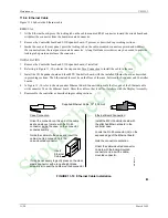
There are two Controller board versions. Figure 11-2 shows an MPU Controller board with jumpers W2, W4 and 

W8

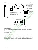
. Figure 11-3 shows an MPU Controller board with jumpers W2, W4, and 

W7

.  These jumpers are factory set 

but may need to be changed in the field.  W2 and W4 are discussed in Section 11.5.5 Accessory Boards.  W7 and 
W8 settings are described in the figures and in Section 11.5.3 MPU Controller Board. 
 

ETHERNET BOARD LED’s 

 
The board has 5 green LEDs and one red LED

18

. Green LEDs announce status and the red LED flashes to indicate 

an error code. LEDs are visible after freeing the Display Assembly and holding it slightly to one side of the case. 
The LEDs are: 

• 

ACT - Flashes when there is Ethernet activity. It glows steadily when there is an Ethernet connection but 
no activity and extinguishes when there is no Ethernet connection. 

• 

F/H - Lighted for Full duplex and off for Half duplex. 

• 

100 - Lighted for 100 MB network and off for 10 MB network 

• 

ST - Lighted during Self-Test and off in normal operation. 

• 

Modbus - When lighted, the green LED indicates an operating Modbus board. The red LED will normally 
be off. When an error exists, the red LED will flash one second on/one second off with a 5 second pause. 
Count the number of flashes between two pauses. 

1 flash - Data bus test failure 
2 flashes - Address bus test failure 
3 flashes - Data read/write test failure 
4 flashes - Register 40001 test failure 
5 flashes - Register 40070-40077 test failure 
6 flashes - Flash CRC test failure 
The board is not user serviceable. 

 
The Ethernet board’s LED power-up sequence is listed below. It is assumed that an Ethernet connection exists. The 
ST and Modbus LEDs will flash in the following sequence. 

1.  Both Modbus LEDs and the ST LED light. 

2.  The red Modbus LED remains lighted while the other two extinguish. The flashing red LED during a normal 

startup is not an error indication. The ACT LED will light. 

3.  The red Modbus and ACT LEDs extinguishes and the green Modbus and ST LEDs light. 

4.  The green Modbus LED remains lighted and the ST LED extinguishes. 

5.  The Act LED begins to flash, the F/H and 100 LEDs go to the link values, and the green Modbus LED remains 

lighted. 


18

 An Ethernet board illustration was not available at the time this manual was printed. 

StockCheck.com

Содержание Moore 353

Страница 1: ... Automation UM353 1 Rev 11 March 2003 Supersedes Rev 10 4 2 4 5 3 T C2 0 5 3 P PB1 PB2 A M ACK L S D UNITS LOOP S P CLOSE OPEN 0 100 20 40 60 80 100 0 2 X03141S2 Moore 353 s PROCESS AUTOMATION CONTROLLER S t o c k C h e c k c o m ...

Страница 2: ...S t o c k C h e c k c o m ...

Страница 3: ...BLOCKS 3 3 3 1 1 FCO LIB Factory Configuration Library 3 3 3 1 2 SECUR Security 3 3 3 1 3 STATN Station Parameters 3 5 3 1 4 CLOCK Real Time Clock V2 0 2 2 3 7 3 1 5 ETHERNET Ethernet Communication Network V2 4 3 7 3 2 I O AND LOOP FUNCTION BLOCKS 3 8 3 2 1 A M A M Transfer 3 8 3 2 2 ACS ARCCOSINE 3 10 3 2 3 ADD_ Addition 3 10 3 2 4 AG3 AGA 3 Orifice Metering of Natural Gas 3 11 3 2 5 AG7 AGA 7 Me...

Страница 4: ... 2 46 DYT_ Delay Timer 3 52 3 2 47 E I External Internal Transfer Switch 3 53 3 2 48 ESL Events Sequence Logger 3 54 3 2 49 EXP_ NATURAL EXPONENTIATION 3 55 3 2 50 EXT_ EXPONENTIATION 3 55 3 2 51 FTG_ Falling Edge Trigger 3 56 3 2 52 GB_ Gain Bias 3 56 3 2 53 HLD_ Hold 3 56 3 2 54 ID ID Controller 3 57 3 2 55 LL_ Lead Lag 3 58 3 2 56 LMT_ Limit 3 58 3 2 57 LN_ NATURAL LOGARITHM 3 59 3 2 58 LOG_ LO...

Страница 5: ...CO101 Single Loop Controller w Tracking Setpoint 4 2 4 2 FCO102 Single Loop Controller w Fixed Setpoint 4 3 4 3 FCO103 External Set Controller with Tracking Local Setpoint 4 4 4 4 FCO104 External Set Controller with Non Tracking Local Setpoint 4 6 4 5 FCO105 Ratio Set Control w Operator Setpoint Limits 4 8 4 6 FCO106 Single Loop Controller w Operator Setpoint Limits 4 10 4 7 FCO107 Dual Loop Contr...

Страница 6: ...e Connectors and Covers 8 3 8 3 2 Panel and Rack Mounting Guidelines 8 5 8 3 3 Station Mounting 8 7 8 4 ELECTRICAL INSTALLATION 8 8 8 4 1 Wiring Guidelines 8 8 8 4 2 Analog Signal Input Wiring 4 20 mA 1 5 Vdc and mV 8 13 8 4 3 Analog Output Wiring 4 20 mA 1 5 Vdc 8 15 8 4 4 Digital Input and Output Wiring 8 16 8 4 5 Thermocouple Input Wiring 8 18 8 4 6 RTD Input Wiring 8 19 8 4 7 Ohms and Slidewir...

Страница 7: ...12 2 ANALOG OUTPUT AOUT1 3 12 3 13 0 CIRCUIT DESCRIPTION 13 1 13 1 OVERVIEW 13 1 13 2 MPU CONTROLLER BOARD 13 2 13 3 I O EXPANDER BOARD 13 2 13 4 LonWorks BOARD 13 3 13 5 LOCAL INSTRUMENT LINK LIL NETWORK BOARD 13 3 13 6 ETHERNET BOARD 13 3 14 0 MODEL DESIGNATION AND SPECIFICATIONS 14 1 14 1 MODEL DESIGNATION 14 1 14 2 ACCESSORIES 14 3 14 3 SERVICE PARTS KITS 14 4 14 4 MECHANICAL SPECIFICATIONS 14...

Страница 8: ... Digital Inputs DIN and DINU 8 16 8 15 Digital Output DOUT1 Resistive and Inductive Loads 8 17 8 16 Universal Analog Input AINU1 Thermocouple Input 8 18 8 17 Reference Junction Lead Forms 8 18 8 18 Universal Analog Input AINU1 2 3 and 4 Wire RTD Inputs 8 19 8 19 Universal Analog Input AINU1 Ohms Input 8 20 8 20 Universal Analog Input AINU1 Slidewire Input 8 20 8 21 Universal Relay Outputs ROUT1 an...

Страница 9: ...hanges for Rev 11 are indicated by change bars in the outside page margins Some of these changes are listed below SECTION CHANGE Cover Changed to Rev 11 March 2003 1 Introduction Table 1 1 Contact Information updated 2 Configuration Overview Ethernet function block list in Section 2 5 updated 3 Function Blocks AIE CIE DIE ODA ODC ODD ODP ODS and RLM blocks updated AWE CWE and DWE blocks added 11 M...

Страница 10: ...umes no liability for errors or omissions in this document or for the application and use of information included in this document The information herein is subject to change without notice Procedures in this document have been reviewed for compliance with applicable approval agency requirements and are considered sound practice Neither Siemens Energy Automation Inc nor these agencies are responsi...

Страница 11: ... an action that should be taken to avoid an undesirable result or state Note Identifies additional information that should be read Electrical shock hazard The included Warning text states that the danger of electrical shock is present Electrical shock hazard Indicated that the danger of electrical shock is present Explosion hazard Indicates that the danger of an explosion hazard exists Electrostat...

Страница 12: ...tion or maintenance Should further information be desired or should particular problems arise which are not covered sufficiently for the purchaser s purposes the matter should be referred to one of the support groups listed in the Product Support section of this manual The contents of this manual shall not become part of or modify any prior or existing agreement commitment or relationship The sale...

Страница 13: ...handling precautions are needed A properly grounded conductive wrist strap must be worn whenever an electronics module or circuit board is handled or touched A service kit with a wrist strap and static dissipative mat is available from Siemens PN15545 110 Equivalent kits are available from both mail order and local electronic supply companies Electronic assemblies must be stored in anti static pro...

Страница 14: ...Contents UM353 1 xii March 2003 S t o c k C h e c k c o m ...

Страница 15: ...chanical and electrical installation Electrical connections to the controller are identified and numerous wiring diagrams are included Section 9 Local Faceplate Operation describes and illustrates the Display Assembly s operator controls and displays Use of these for on line operation for configurations and for autotuning is described Section 10 Controller and System Test has procedures for testin...

Страница 16: ...thernet Network Board RTC CB or RCB Board Future Use LonWorks Board Accessory or Option Boards FIGURE 1 1 Moore 353 Exploded View Modbus communication is standard and a port RS485 half duplex at the rear terminals provides for network connection of up to 32 controllers e g Models 352P 353 354 354N and Procidia i pac to an operator workstation Human Machine Interface HMI or DCS enabling integration...

Страница 17: ...y with an array of network enabled products including those listed below Current Controller Models Previous Controller Models Procidia i pac Internet Control System Moore 352P Single Loop Digital Controller Model 352 Single Loop Digital Controller Model 351 Triple Loop Digital Controller Moore 354 354N Universal Controllers Model 382 Logic and Sequence Controller An optional Ethernet board is avai...

Страница 18: ...thin each loop e g controller setpoint auto manual others can be used as many times as needed Some notable features include Auto Tuning within the PID function blocks an expandable Sequencer that allows configuration of up to 250 steps and up to 256 discrete inputs and outputs In addition the Graphical Configuration Utility can be used to design the logic in a ladder diagram Combining these featur...

Страница 19: ... to provide a method for sending and receiving both analog and discrete data to and from remote devices over the remote I O digital bus Each use will automatically be assigned a unique name e g AIP01 AOP01 within the station so that the unique block name becomes loop block e g TC2053 AIP01 for Analog Input lev_Percent used in loop TC2053 The second AIP block used within the station will be assigne...

Страница 20: ...value until the Exit button is pressed This will enable bumpless changes to be made while on line The second method is to use the Graphical Configuration program A configuration can be downloaded to a controller either via the port on the local faceplate or over a network either Modbus Ethernet or LIL During a download all outputs will be held and the controller will retain all the intermediate ca...

Страница 21: ...cted to ensure proper operation It is then packaged for shipment Most accessories are shipped separately 1 4 2 Receipt of Shipment Inspect each carton at the time of delivery for possible external damage Any visible damage should be immediately recorded on the carrier s copy of the delivery slip Carefully unpack each carton and check the contents against the enclosed packing list Inspect each item...

Страница 22: ... a Moore 353 with Expansion Board option 1 is ordered When adding an I O Expander board to a Standard Case case Option 2 with black Side Entry Connectors order connector kit PN 16353 133 to obtain terminals 27 52 When adding an I O Expander board to a Standard Case with Ethernet connector case Option 4 with gray or green Direct Entry Connectors no additional connectors need be ordered For field in...

Страница 23: ...mA to 15 75 mV Range Resistor 3 75Ω 0 1 3W WW 2 Sleeving 5 Crimp On Connector 6 TC Reference Junction 100Ω 2 Kit Installation Instruction 1 5 UM353 1 Moore 353 User s Manual this manual qty 1 6 Additional items as required by your order Refer to the packing list accompanying a shipment S t o c k C h e c k c o m ...

Страница 24: ...Introduction UM353 1 March 2003 1 10 S t o c k C h e c k c o m ...

Страница 25: ... CB board ETHERNET Ethernet Communications requires firmware 2 4 and Ethernet board 2 2 STATION HARDWARE I O BLOCKS Function blocks that are available during configuration depend on the hardware installed in the controller These blocks can be selected within a LOOP but as fixed resources once selected are no longer available The left column shows the minimum and maximum quantities of each block an...

Страница 26: ... Operator Display for Pushbuttons ONOFF ON OFF Controller OR01 99 OR Logic ORSL Override Selector OST01 99 One Shot Timer PB1SW PB1 Switch PB2SW PB2 Switch PB3SW PB3 Switch PCOM Phase Communication V1 3 PD PD Controller PID PID Controller PIDAG PIDAG Controller PRSEQ Program Sequencer QHD01 99 Quickset Hold RATIO Ratio RCT01 99 Repeat Cycle Timer RLM01 99 Rate Limiter V3 0 ROT01 99 Retentive On Ti...

Страница 27: ...S1 6 Digital Input_State V1 3 AOP01 25 Analog Output lev_Percent DOD1 6 Digital Output lev_Discrete 16 Channels DID1 6 Digital Input lev_Discrete 16 Channels DOS1 6 Digital Output_State V1 3 2 7 CONFIGURATION PROCEDURE Each controller must be configured to perform the desired control strategy The arrangement of functions and the numerical data required for a particular control circuit are referred...

Страница 28: ...elected FCO and to enter or edit parameter values 1 Press the ENTER EXIT CONF button LOOP will appear on the alphanumeric display 2 Rotate the Pulser Knob until STATION appears on alphanumeric display 3 Press the STEP DOWN button to display FCO LIB 4 Press the STEP DOWN button to display FCO in the lower display 5 Press the STEP DOWN button until the desired FCO number appears in numeric display 6...

Страница 29: ...g the installed MPU Controller board firmware with an earlier version may be desired Before loading the earlier firmware refer to the sections on configuration and load FCO 0 zero as the active configuration This will install a minimum configuration and will reduce the number of error messages that appear during the firmware loading process 2 8 OPERATION DURING LOCAL ON LINE CONFIGURATION Changing...

Страница 30: ... SECURITY LEV1 COM X 000000 X STORE CAL AIN1 X CAL ZERO X STORE CAL X CAL ZERO TC2053 Alphanumeric Display 325 80 Numeric Display Configuration Pushbutton 008 Display with changeable value turn Pulser knob Turn Pulser to select new parameter or value move horizontally across map X Use Step Up or Step Down pushbutton move vertically across map Key Turn Pulser to select additional menu items X03137S...

Страница 31: ...greatest resolution between 0 00000 and 999999 or 0 0000 and 99999 Numbers outside this resolution will blink Analog outputs are typically output 01 for analog I O blocks and math functions Analog outputs may also be specific to a particular function block such as the Analog Output AO Step Number SN Step Time ST Remaining Time RT and Current Recipe CR outputs of the Program Sequencer 3 Arrows with...

Страница 32: ... 0 5000 when displaying the process The A M block AOUT1 Valve output and the Valve input of the ODC block are scaled based on the output of the PID block FCO104 External Set PID controller The external setpoint is displayed as variable X in the ODC block Therefore the ODC RX input uses the range output of the external setpoint AIN2 OR for scaling The 0 100 bargraph will represent the range of AIN1...

Страница 33: ...uration is edited 3 1 2 SECUR Security The SECUR function block enables a user to lock out portions or all of the faceplate configuration functions Five levels of security are available see Table 3 1 Each level is factory set to 000000 no security and can be changed by the user in the field to any number up to 999999 A security combination should be assigned to each security level 1 highest 5 lowe...

Страница 34: ...on If a combination is lost contact Siemens technical support to obtain a method to enter configuration and change the security codes Refer to Section 1 3 for the contact information The PC based Graphical Configuration Software may also have security options similar to the above However there is no security in the download procedure itself At the controller there are parameters in function block ...

Страница 35: ... to change the station identification without being aware of system consequences There are two timers used during power up initialization WARM TIM and COLD TIM The station takes approximately 8 seconds to perform power up initialization before the power up time is evaluated A timer should be set to a value greater than 8 seconds to be effective A timer setting of 0 will be considered as infinite e...

Страница 36: ...evision The controller s operating Kernel and operating code reside on the MPU Controller board and there is an entry in the table for each The table lists the hardware and software revisions For example in Table 3 3 the MPU Controller board would be shown in the numeric display as 11 1 00 TABLE 3 3 Board Description and ID with Example Hardware and Software Revisions BOARD DESCRIPTION BOARD ID HA...

Страница 37: ...nd synchronize its time with the master 3 1 5 ETHERNET Ethernet Communication Network V2 4 The ETHERNET function block is available when the Ethernet Communication Network option board is installed in the controller and the controller includes firmware version V2 4 or higher Use this function block to configure Ethernet communication parameters The default IP addresses shown are used for factory t...

Страница 38: ...defines the range of the manual function as 10 to 110 This can be useful to prevent inadvertent changes from an operator workstation that might set the manual value well beyond the local operator s changeable range In most cases the Range input range pointer will connect to the controller function block An unconfigured range pointer will default the range to 0 00 100 00 BLOCK DIAGRAM A R G AS A EM...

Страница 39: ... manual value to increase with clockwise rotation of the knob This feature is useful when clockwise rotation is desired to always open a value whether the valve is direct or reverse acting EMergency MANual in firmware 1 30 and higher allows the position of the A M block Manual Switch switch 1 in the block diagram and the associated light to be configured When the EM input goes high 1 the Emergency...

Страница 40: ...its are not consistent an SCL Scaler function block can be used or an alternative is to use a MATH function block that has built in scaling functions BLOCK DIAGRAM A O1 B C Input X ARCCOSINE O1 Output 1 O1 ACOS X ACS ESN 000 X E Exec Seq No 000 to 250 000 X T U P N I INPUT X loop tag block tag output null S N BLOCK DIAGRAM O1 X Input X Output 1 ACOS X Input A ADDITION O1 Output 1 ADDITION ADD_ ESN...

Страница 41: ... 1 0 75 and Re Reynolds Number is 4000 or larger Y expansion factor and absolute flowing pressure Pf are referenced to upstream tap i e Y1 Pf1 hw is in inches H20 and Pf is in psia 0 hw 27 707 Pf 0 2 The following parameters are configuration entries dr orifice plate bore diameter in inches at a reference temperature of 68 F Dr meter tube internal diameter in inches at a reference temperature of 6...

Страница 42: ... factors Zs Zf Zb can be entered manually using HLD Hold function blocks computed and then downloaded from a host device or calculated in the controller using the AG8 AGA 8 Compressibility Factors of Natural Gas function block The following are analog outputs of the AGA 3 function block Qb volume flow rate at base conditions SCFH Standard Cubic Feet per Hour C composite orifice flow factor SCFH ps...

Страница 43: ...ated continuously and is the volume flow rate at base conditions in the same units as input Qf Tb and Tf are converted within the block from F to R adds 459 67 to the F input value for the actual calculation Compressibility factors Zf Zb can be entered manually using HLD Hold function blocks computed and downloaded from a host device or calculated in the controller using the AG8 AGA 8 Compressibil...

Страница 44: ...s and the scan cycle of the controller AGA 8 Zs Output Zs AGA 8 AG8 ESN 000 Exec Seq No 000 to 250 000 Input Pf Pf Input Tf Tf P f T U P N I T U P N I H T M E P b f T T b E S E N INPUT Tf loop tag block tag output null INPUT Pf loop tag block tag output null base Pressure psia Real 14 73 base Temperature deg F Real 60 0 A N Zf Output Zf Zb Output Zb Gr Output Gr METHANE composition Real 96 5222 R ...

Страница 45: ...of the source device The MB ADRES parameter allows a Modbus address to be configured When connecting to other Siemens MOORE controllers the Modbus address is set to 1 In some cases other devices may use a different address or when going through a Modbus TCP IP gateway a Modbus network may have multiple devices each having a unique address The REG TYP parameter allows setting the source register as...

Страница 46: ... 65535 Sint MIN INT 32768 Sint MAX INT 32767 TABLE 3 FB Numbers vs Modbus Registers FB Number MB Register FB Number MB Register FB Number MB Register FB Number MB Register AOE01 30961 AOE09 30977 AOE17 30993 AOE25 31009 AOE02 30963 AOE10 30979 AOE18 30995 AOE26 31011 AOE03 30965 AOE11 30981 AOE19 30997 AOE27 31013 AOE04 30967 AOE12 30983 AOE20 30999 AOE28 31015 AOE05 30969 AOE13 30985 AOE21 31001 ...

Страница 47: ...or a misconfiguration of the source The AIL function can be assigned to a single LIL channel It will then have certain data that will be accessible over the LIL Parameter 1 is the received data RD in the 80 F80 format and will be re transmitted by this station on the assigned channel This LIL CHAN parameter can also be set to 0 The controller will still receive global data from the other station b...

Страница 48: ... when good Bad quality signifies an A D conversion failure or a 1 5Vdc input signal that falls below 0 6 Vdc indicating an open circuit or failure of a 2 wire transmitter A verify mode is available during calibration to view the analog input in volts over the full calibrated range The input is factory calibrated for 1 5 Vdc and should not require field calibration However field calibration can be ...

Страница 49: ...ts must be adjusted to meet a local standard a field calibration feature is available to override the factory calibration for the input type selected The factory calibration is retained so that the input can be returned to the factory calibration at any time by storing FAC in the calibration selection Table 3 5 provides the input values that are used to perform a field calibration A verify mode is...

Страница 50: ...00 C 6 RT C Type R Thermocouple 18 C to1610 C 0 F to 2930 F 400 C 1400 C 7 BT C Type B Thermocouple 18 C to 1815 C 0 F to 3300 F 800 C 1600 C 8 NT C Type N Thermocouple 185 C to 1300 C 300 F to 2370 F 0 C 1000 C 9 DRTD DIN 43760 IEC 751 RTD alpha 0 003850 185 C to 622 C 300 F to 1152 F 100Ω 0 C 285Ω 512 380 C 10 URTD US NBS 126 RTD alpha 0 003902 185 C to 613 C 300 F to 1135 F 100Ω 0 C 285Ω 504 84...

Страница 51: ...can be viewed in the configuration mode This is useful when other devices need this for binding The Output Range is a special data type that includes the MIN and MAX SCALE the DPP and the ENGUNITS that can be connected to other blocks with a Range RG PTR input The block output QS indicates the quality status of the output signal O1 and will go high when the output is of bad quality Bad quality usu...

Страница 52: ...ave the following features Deadband requires that the signal either drop below or exceed the limit setting by the amount of the deadband before the alarm clears goes low The alarm deadband is set as a fixed of the range pointer scale Delay In Time requires that the input remain above or below the limit setting for the delay time before the alarm trips goes high This can help prevent nuisance alarm...

Страница 53: ...he limit setting minus the deadband OR compares the process input with the range limits referenced by the range pointer parameter and will trip the alarm status high 1 when the process is equal to or greater than the high limit or equal to or less than the low limit The alarm status will clear 0 when the process is less than the high limit minus the deadband or greater than the low limit plus the ...

Страница 54: ... be set to 1 when events occur and at least one within the loop has not yet been acknowledged It can be reset to 0 which will acknowledge all events within the loop or when 0 will indicate all active events have been acknowledged BIT 15 14 13 12 11 10 9 8 7 6 5 4 3 2 1 0 1 AE NA CC OS E4 N4 A4 E3 N3 A3 E2 N2 A2 E1 N1 A1 0 3 2 13 AND_ AND Logic AND_ function blocks perform a logical AND on the thre...

Страница 55: ...numbers are assigned in sequence with each use station wide The configuration requires the entry of a LIL Channel number to which the data is to be assigned The range pointer parameter input R enables the block to scale the LIL global output GO in the standard 80 F80 range for the range of input S If the pointer is not configured the value will be scaled as 0 00 to 100 00 1 2 3 4 5 6 7 8 9 10 11 2...

Страница 56: ...gnal will be scaled and transmitted on the network as a SNVT_lev_percent SNVT 81 data type The NV NUM parameter enables viewing the output variable number This may be needed when using a remote PC network manager to bind this output with the network variable in a remote node The block output QS indicates the quality status of the Lon output and will go high when the output is of bad quality Bad qu...

Страница 57: ...and should not require field calibration However field calibration can be performed if desired The output is calibrated by adjusting the pulser until the desired output i e 4 0 mA for zero is obtained and then pressing the store button A verify mode is available during calibration that will show the mA value in the numeric display as the pulser adjusts the output over the full range Output QS is t...

Страница 58: ...oftware can display trend data on a Loop Detail screen or Analog Detail screen Parameter TRND TYP allows data to be stored in one of two formats the average over each sample time or the peak peak values of the data over each sample time All data is stored in a normalized form based on the value of the RG PTR range pointer input The range information will be part of the data packet when retrieved o...

Страница 59: ...rmware 1 30 and higher output a signal in radians of which the input is the tangent Input X ARCTANGENT O1 Output 1 O1 ATAN X ATN ESN 000 X E Exec Seq No 000 to 250 000 X T U P N I INPUT X loop tag block tag output null S N BLOCK DIAGRAM O1 X Input X Output 1 ATAN X S t o c k C h e c k c o m ...

Страница 60: ...eger Sint options are available See the table listing parameters and default values below The IP ADRES parameter is used to configure the IP address of the destination Modbus device The MB ADRES parameter allows a Modbus address to be configured When connecting to other Siemens MOORE controllers the Modbus address is set to 1 In some cases other devices may use a different address or when going th...

Страница 61: ...e direct acting and will cause outputs A1 or A2 to go high when the integrated total is equal to or higher than the preset If set to NO the total will cause A1 or A2 to go high when the total is equal to or lower than the preset The actual preset value is available on outputs T1 and T2 The function block can also provide a pulse output to drive a remote counter The pulse output function integrates...

Страница 62: ...r block to be used with another function block such as the DINU that provides a count signal When input A is not configured it will be set to 0 0 The EC input is summed with the initial value for use as the total This value will now be displayed as the total on the operator faceplate and the presets will act on this value to provide outputs A1 and A2 BLOCK DIAGRAM 1 BATCH TOTALIZER A t dt A PRESET...

Страница 63: ... maintains controller output at the batch switch limit setting and eliminates reset windup If a controller has a large proportional gain setting the reset can be modified too much such that the process may under shoot the setpoint during a startup condition The BPL Batch Pre Load is adjusted to optimize the controller for startup conditions by limiting how much the batch switch can adjust the cont...

Страница 64: ...ure if the parameter QUICKSET is set to YES The BIAS value will continuously change as the knob is adjusted but the STORE button must be pressed when the final value is reached to insure that the new BIAS setting will be retained on a Cold power up condition Any unused inputs to the block will be set equal to 0 The TO Tracked Output is normally used in applications where an external device is bein...

Страница 65: ...o be configured When connecting to other Siemens MOORE controllers the Modbus address is set to 1 In some cases other Modbus devices may use a different address or when going through a Modbus TCP IP gateway a Modbus network may have multiple devices each having a unique address The START CL parameter identifies the location of the first Coil Subsequent Coils up to 16 can be obtained by setting the...

Страница 66: ... limit Dead BAND for reverse action EXTERNAL LIMIT When input EL is configured the LIMIT setting will be ignored and the value of input EL will be used as the limit value Input X CHARACTERIZER 0 Input Coordinate X0 S Real 0 0 OY Output Y CHR_ ESN 000 X X CHARACTERIZER Exec Seq No H 001 to 250 S E N 1 Input Coordinate X1 S Real 10 0 X 2 Input Coordinate X2 S Real 20 0 X 3 Input Coordinate X3 S Real...

Страница 67: ...OSINE COS_ function blocks in firmware 1 30 and higher accept radian inputs and output the cosine of that angle 3 2 29 CWE_ Coil Write Ethernet V3 0 CWE_ function blocks are available when the optional Ethernet communication board9 is installed in the controller It enables the controller to write Coil data to other stations over the Ethernet network Up to 32 CWE_ blocks are available Blocks are as...

Страница 68: ...ite is not completed successfully This is normally associated with failure of the destination device to receive data due to a communication failure or a misconfiguration of the device 3 2 30 DAM_ Deviation Amplifier DAM_ function blocks compute the difference between inputs A and B amplify the difference signal and sum the resultant with an internal BIAS and an external signal at input C Unused in...

Страница 69: ...ted in the block diagram A mode of 0 is Normal and 1 is Forced Each function block output also has a quality status associated with it This status will go high 1 when the block determines it has lost communication with the Lon node If any of the individual quality outputs are high the Quality Status block output will also be high DIGITAL INPUT LEV_DISCRETE O0 Output 0 DIGITAL INPUT DID_ QS Quality...

Страница 70: ...entifies the location of the digital data in the source device The REG TYP parameter enables reading of Holding Registers Modbus Function Code 03 or Input Registers Modbus Function Code 04 Both are treated the same in most Modbus devices but the Input type is the most common usage The use of DOE blocks in other Siemens MOORE controllers as the input source is defined by using the Modbus Registers ...

Страница 71: ... QS indicates the quality of the received data and will go high 1 when the data is bad This is normally associated with failure to receive global data due to a LIL failure or a misconfiguration of the source The received global word will also be re transmitted by this station as a parameter 1 value in the configured channel n 1 2 3 4 5 6 7 8 9 10 11 12 n GW SA SC DISCRETE WORD INPUT LIL DISCRETE W...

Страница 72: ... block names IDs and terminal designators are listed in Section 8 4 The block output is high 1 when the input is on and low 0 when off Output QS indicates the quality status of the output signal O1 and will be high 1 when the output is of bad quality Bad quality indicates any hardware failure of the input converter DIN_ DIN_ DIGITAL INPUT _ DIGITAL INPUT DIN_ O1 Output 1 QS Quality Status BLOCK DI...

Страница 73: ...backwards including negative values The direction input feature enables the use of count down counters and it allows duplication of functions performed by previous computer pulse interfaces having a Pulse Direction format Input TC asserted high 1 will force the scaled count to track an external signal This can be used in applications where the CT output is being used to set a value e g setpoint th...

Страница 74: ...e associated with it The mode can be either NORMAL or FORCED When using a PC capable of sending LIL or Modbus commands the mode can be changed and the forced state can be assigned a high 1 or low 0 value The values accessible over the network are the two switch inputs N and F and the position of the SPDT switch illustrated in the block diagram A mode of 0 is Normal and 1 is Forced The function blo...

Страница 75: ...d will return to a low 0 output on the succeeding positive transition POWER UP During a hot or a warm start with PU LAST set to YES the block will retain the last count and continue at the last input output states If set to NO during a warm or a cold start the output and count will be initialized to 0 Numerator DIVISION O1 Output 1 DIVISION DIV_ ESN 000 N E Exec Seq No H 001 to 250 D T U P N I INP...

Страница 76: ...ity status associated with it This status will go high 1 when the block determines it has lost communication with the Lon node bound to that input If any of the individual quality inputs are high the Quality Status block output will also be high QS Quality Status QF Input F F Quality F Q0 Input 0 0 DIGITAL OUTPUT LEV_DISCRETE DIGITAL OUTPUT DOD_ LEV_DISCRETE LonWorks Network U N V N M I N P U T 0 ...

Страница 77: ...obal word GW with bits 0 F representing the state 1 or 0 of each of the Boolean inputs D0 DF Unconfigured inputs are set to 0 DOL block numbers are assigned in sequence with each use station wide 1 2 3 4 5 6 7 8 9 10 11 12 n GW IF I0 DIGITAL OUTPUT ETHERNET DIGITAL OUTPUT DOE_ Input F I N P U T 0 INPUT 0 H loop tag block tag output null Input 0 ETHERNET I N P U T 1 I N P U T 2 I N P U T 3 I N P U ...

Страница 78: ...bus commands the mode can be changed and the forced state can be assigned a high 1 or low 0 value The values accessible over the network are the two switch inputs N and F and the position of the SPDT switch illustrated in the block diagram A mode of 0 is Normal and 1 is Forced The function block also has a quality status associated with it This status will go high 1 when the block determines it ha...

Страница 79: ...h will turn on when the block input S is high 1 and will turn off when low 0 Two digital output function blocks are available on the Controller Board Terminal Connections DOUT1 DOUT1 8 DOUT1c 9 DOUT2 DOUT2 10 DOUT2c 9 DOUT_ DOUT_c DIGITAL OUTPUT _ DIGITAL OUTPUT DOUT_ Switch I N P U T S INPUT S H loop tag block tag output null Open Collector Transistor Switch S BLOCK DIAGRAM S RELAY 24 V dc Typica...

Страница 80: ...gh 1 will enable the operation of the DTM block When this input is not configured it will be set high A low 0 input will cause all registers and the outputs to equal the input A POWER UP During a warm or cold start all outputs will be initialized at 0 and all registers will be initialized to the value of the input on the first scan BLOCK DIAGRAM A O1 SHIFT REGISTERS E AT Adaptive Time Analog Input...

Страница 81: ...the Ethernet network Up to 32 DWE_ blocks are available Blocks are assigned in sequence controller wide with each use Digital data is On Off data packed into a 16 bit word The IP ADRES parameter is used to configure the IP address of the destination Modbus device The MB ADRES parameter allows a Modbus address to be configured When connecting to other Siemens MOORE controllers the Modbus address is...

Страница 82: ...the scan time of the station the delay time will equal the scan time Output ET elapsed time will ramp from 0 0 to the value of DLY TIME and remain there until P resets the output Output RT remaining time equals DLY TIME ET POWER UP During a warm or a hot start with PU LAST set to YES the block will initialize with the input output states and elapsed time in effect at the instant power down occurre...

Страница 83: ... temporarily select the Internal Input as the function block output O1 This input does not affect the position of the E I switch Outputs SE and SI indicate the actual position of the E I switch SE is HI 1 when in the E position and LO 0 when in the I position SI is HI when in the I position and LO when in the E position Outputs IS and ES indicate the actual source of the block output IS is HI when...

Страница 84: ...et The configured 8 character name will be shown in the alphanumeric display and the order of occurrence ESL 1 ESL 2 will appear in the numeric display when stepping through the event log Other events such as alarms status conditions or errors can be similarly viewed if logged to the ESL function block 01 02 23 R HI PRESS V1CLOSED V1 OPEN PUMP OFF 1 2 3 4 5 6 7 8 EVENT SEQUENCE LOGGER Block Diagra...

Страница 85: ...ve values of input Y will be treated as 0 0 When input Y is 0 0 and X is negative the output will be set to the maximum number i e 1 17 e38 Input X NATURAL EXPONENTIATION O1 Output 1 O1 e EXP ESN 000 X E Exec Seq No 000 to 250 000 X T U P N I INPUT X loop tag block tag output null S N X BLOCK DIAGRAM O1 X Input X Output 1 eX Input X EXPONENTIATION O1 Output 1 O1 Y EXT ESN 000 X E Exec Seq No 000 t...

Страница 86: ... BO 3 2 53 HLD_ Hold HLD_ function blocks provide an output equal to the HOLD VAL set in configuration for interconnection to other function blocks Pulse Input FALLING EDGE TRIGGER O1 Output 1 FALLING EDGE FTG_ ESN 000 P E S N Exec Seq No H 001 to 250 P T U P N I INPUT P H loop tag block tag output null TRIGGER BLOCK DIAGRAM Output 1 P O1 Pulse Input Input A GAIN BIAS N G I N U A OUTput GAIN S Rea...

Страница 87: ...er is not configured the controller will use a range scaling of 0 00 100 00 POWER UP During a warm or cold start the output will be initialized to the value of the MINSCALE parameter and all dynamic states will be initialized to their current input value on the first scan cycle t D S t D DG S 1 e A t I S 1 1 O1 F P S BLOCK DIAGRAM Absolute Value AE 1 A Auto Setpoint Process Abolute Error Output 1 ...

Страница 88: ... If the input exceeds one of the limits the block will output the limit value If the HI LIMIT is set lower than the LO LIMIT the block will output the high limit value The output statuses will be high 1 when the block is in a limit condition BLOCK DIAGRAM HI SELECTOR LO SELECTOR HI LIMIT A O1 LO LIMIT HS LS Output 1 High limit Status Low limit Status BLOCK DIAGRAM O1 E A tLead 1 tLag 1 Enable Anal...

Страница 89: ...n blocks in firmware 1 30 and higher will output the logarithm to the base 10 of input X When the input is 0 0 the input will be treated as the smallest number greater than 0 0 i e 1 17 e 38 and the LOG will be computed accordingly BLOCK DIAGRAM O1 X Input X Output 1 LOG10 X Input X LOGARITHM BASE 10 O1 Output 1 O1 LOG X LOG ESN 000 X E Exec Seq No 000 to 250 000 X T U P N I INPUT X loop tag block...

Страница 90: ... by the numerator If the numerator is 0 the output will be 0 O1 A C BLOCK DIAGRAM Output 1 INput A MATH BIAS INput B GAIN INput C GAIN INput A GAIN INput B BIAS INput C BIAS OPeration A Add Sub Mul Div OPeration B Add Sub Mul Div OUTput GAIN OUTput BIAS B Input C Input B Input A Input A MATH N OUTput GAIN S Real 1 0 O1 Output 1 ADD SUB MUL DIV MTH_ ESN 000 I A A B C MATH Input B Input C INPUT C H ...

Страница 91: ...TRUTH TABLE A B C Output 1 0 0 0 0 0 0 0 0 0 0 0 0 1 1 1 1 0 1 1 1 1 1 1 1 1 NAND 1 1 1 1 1 1 1 Input A MULTIPLICATION O1 Output 1 MULTIPLICATION MUL_ ESN 000 A E S N Exec Seq No H 001 to 250 C T U P N I INPUT B H loop tag block tag output null Input B B B T U P N I INPUT C H loop tag block tag output null Input C C A T U P N I INPUT A H loop tag block tag output null NAND Input A NAND O1 Output 1...

Страница 92: ...Output 1 0 0 0 0 0 0 0 0 0 0 0 0 1 1 1 1 1 1 1 1 1 1 1 1 NOR 1 0 0 0 0 0 0 0 NOT O1 Output 1 NOT NOT_ ESN 000 E S N Exec Seq No H 001 to 250 A INPUT A H loop tag block tag output null I T U Input A A P N BLOCK DIAGRAM O1 Output 1 A Input A Input A NOR O1 Output 1 NOR NOR_ ESN 000 A E S N Exec Seq No H 001 to 250 C T U P N I INPUT B H loop tag block tag output null Input B B B T U P N I INPUT C H l...

Страница 93: ... 4 RanGe PoinTeR S loop tag block tag null 1 A L I M I T 1 B L I M I T Process 1 Alarm A LIMIT S Real 110 0 Process 1 Alarm B LIMIT S Real 10 0 2 A L I M I T 2 B L I M I T Process 2 Alarm A LIMIT S Real 110 0 Process 2 Alarm B LIMIT S Real 10 0 3 A L I M I T 3 B L I M I T Process 3 Alarm A LIMIT S Real 110 0 Process 3 Alarm B LIMIT S Real 10 0 4 A L I M I T 4 B L I M I T Process 4 Alarm A LIMIT S ...

Страница 94: ...r disabled when in the quickset ALARM mode The configuration allows an alarm to be enabled or disabled on a cold start When an alarm is disabled it will not operate but will retain settings for return to the enabled mode Complete operator faceplate functions relating to alarms are described in the sections describing the specific faceplate design All alarms have the following features Deadband req...

Страница 95: ...play actions using priorities 1 to 5 The horizontal bargraph can be selected as direct or reverse acting This feature allows it to always indicate an OPEN valve when fully lit The labels on the basic faceplate are fixed but paste on labels can be used to change the indications The V NET AC parameter allows the LxVI network parameter to be set for direct or reverse action This enables the valve bar...

Страница 96: ...ch position on the operator faceplate a green LED for C and a red LED for LO Output WD will go high 1 when the controller fails to receive a Modbus network command within the watchdog time The watchdog time is set in the STATN Station Parameters function block Input A can be used to acknowledge all the alarms in all of the loops in a controller Output PN Pulse oN will go high for 0 5 seconds or on...

Страница 97: ... return to the actual output value Operator Display for Discrete indication control I 0 Output 0 INPUT 3 H loop tag block tag output null INPUT 2 H loop tag block tag output null INPUT 1 H loop tag block tag output null INPUT 0 H loop tag block tag output null INPUT 4 H loop tag block tag output null O0 Input 0 TAG S 6 ASCII Char I0 TAG Input 0 0 I T A G I N P U T I I I I N N N N P P P P U U U U T...

Страница 98: ...Function Blocks UM353 1 March 2003 3 68 Manual A M T O F F O n I0 O0 SV 103 Manual A M T O n O n IF OF SV 206 Block Diagram DigDisp1 i ware PC Faceplate Display S t o c k C h e c k c o m ...

Страница 99: ...k in the digital display e g 1 The feedback message associated with this feedback value can be viewed on the local faceplate using the UNITS button The A M button will display the position of the group selector switch and enable switching the group selector switch between auto and manual Operator Display for Pushbuttons 11 Output 11 INPUT 1M H loop tag block tag output null INPUT 1A H loop tag blo...

Страница 100: ...s STOP RUN 1 0 X X AUTO MAN A M Group 1 Message STOP START MS1036 81 82 PB2 PB1 81 82 8A 8M 83 PB3 8F Note Numbers shown on input lines indicate values of unconfigured inputs STOP RUN 1 0 X X AUTO MAN A M Group 8 Message Groups 2 to 7 1 1 1 0 0 1 1 1 0 0 Feedback Messages i ware PC Faceplate Display S t o c k C h e c k c o m ...

Страница 101: ...top and display the first message it comes to Events that require acknowledgment will return the display to the normal mode i e loop tag S and will flash the message When events have been acknowledged they can be viewed using the ACK button The display can be returned to the MSG mode using the D button and will then display the first message in the Queue 5 Output LE is high 1 when a loop event is ...

Страница 102: ...e made from a network command or the local faceplate When CL is configured it can be toggled locally from a pushbutton switch such as PB1SW output PS and will change from local to console or from console computer to local each time the input is toggled Also when output LO goes high output CN will also go high and CM will go low indicating that the control source will change to Console whenever Loc...

Страница 103: ...tputs and comparator functions will be initialized at the state prior to power down and all dynamic elements will be initialized at the current input on the first scan During a cold start all outputs and comparator states will be set to zero to be activated by the block functions All dynamic elements will be initialized at the current input on the first scan t D S t D DG S 1 P S BLOCK DIAGRAM AE S...

Страница 104: ...s when a priority level higher than 0 the default has been selected If an override input is not configured the individual selector will output the other input When no inputs are configured the block will output 0 0 and the OS status will be set low 0 BLOCK DIAGRAM A O1 B C OR TRUTH TABLE A B C Output 1 0 0 0 0 0 0 0 0 0 0 0 0 0 1 1 1 1 1 1 1 1 1 1 1 1 1 OR 1 1 1 1 1 1 Primary Input OVERRIDE SELECT...

Страница 105: ...equal the scan time Output ET elapsed time will ramp from 0 0 to the value of ON TIME and remain there until P goes low 0 Output RT remaining time equals ON TIME ET POWER UP During a warm start when PU LAST is set to YES the block will initialize at the input output states and elapsed time in effect at the instant power down occurred A cold start will initialize the input output states and elapsed...

Страница 106: ...ications such as changing the function of the ODC or ODS function blocks In the sustained mode the switch will alternate positions each time the button is pressed An unconfigured NC input defaults to 0 and an unconfigured NO input to 1 With firmware 1 30 and higher the button can be remotely activated through a command over Modbus or LIL This block operates with an operator faceplate that includes...

Страница 107: ...s such as changing the function of the EITS function block In the sustained mode the switch will alternate positions each time the button is pressed An unconfigured NC input defaults to 0 and an unconfigured NO input to 1 With firmware 1 30 and higher the button can be remotely activated through a command over Modbus or LIL This block operates with an operator faceplate that includes green and red...

Страница 108: ...n when released In the sustained mode the switch will alternate positions each time the button is pressed An unconfigured NC input defaults to 0 and an unconfigured NO input to 1 With firmware 1 30 and higher the button can be remotely activated through a command over Modbus or LIL This block operates with an operator faceplate that includes green and red LEDs that are turned on using input MD A H...

Страница 109: ...gic in Figure 3 1 The W1 or W0 is equivalent to a Mask ON or a Mask OFF using LIL commands All unconfigured inputs will be treated as low 0 except OK RD RN and HE which will be treated as high 1 Three of the output states EO EMERG IK INTRLK and FD FAILED can be configured for priorities 0 5 This will affect the flashing etc as previously described for other controller status conditions These state...

Страница 110: ...ND AND OR ST EN RUN RUN AND HELD RUN R 0 W 1 W 0 F F S R HOLD HO HO AND RUN OR AND EN HO AND HO 13 FD HE R 1 0 HELD AND AND OR HO EN HELD HELD AND RUN HELD R 1 0 DONE DN R 0 W 1 W 0 F F S R PCOMP OR AND RUN AND DONE OR DONE READY AND ABORTED EO DONE R 1 0 ABORTED R 0 W 1 W 0 F F S R ABORT AND HELD AND DONE OR ABORTED ABORTED AND READY IK EN AND ABORTED READY OR AND EO unconfigured 0 unconfigured 1...

Страница 111: ... F P S BLOCK DIAGRAM Absolute Value AE 1 A Auto Initialize I Setpoint Process Absolute Error Output Feedback Lead Lag R INput units Engineering scaling INput units Engineering scaling scaling inverse scaling MR T PD Controller RanGe PoinTeR ENG UNITS Limit 3 3 O 103 3 Process PD CONTROLLER D G DIRect ACTing H NO YES NO O1 Output CONTROLLER PD ESN 000 P S F A PD Setpoint Feedback Auto AE Absolute E...

Страница 112: ...ld deviate from the setpoint during the on off cycles This parameter can be set manually or can be configured as AUTO When AUTO is configured the autotuner will set the DEV to 4 times the HYS This is the minimum value needed to provide good autotuning results The HYS parameter is the amount that the process must deviate from setpoint before switching the output in the opposite direction This value...

Страница 113: ...power up the output will be initialized to MINSCALE and all dynamic elements will be initialized at the current input on the first scan t D S t D DG S 1 e A PG t I S 1 1 O1 F P S BLOCK DIAGRAM Absolute Value AE 1 A Auto Initialize I Setpoint Process Absolute Error Output 1 Feedback Lead Lag R Limit INput units Engineering 3 3 O 103 3 scaling INput units Engineering scaling scaling inverse scaling ...

Страница 114: ...ning results The HYS parameter is the amount that the process must deviate from setpoint before switching the output in the opposite direction This value must be at least equal to or slightly greater than any process noise band If the noise band cannot be determined the autotuner will compute it at the start of an autotuning exercise when the HYS parameter has been configured as AUTO The STEP para...

Страница 115: ...witch block t D S t D DG S 1 e A PG t I S 1 1 O1 F P S BLOCK DIAGRAM Absolute Value AE 1 A Auto Initialize I Setpoint Process Absolute Error Output 1 Feedback Lead Lag R Limit INput units Engineering 3 3 O 103 3 scaling INput units Engineering scaling scaling inverse scaling X AG Adaptive Gain PID Adaptive Gain Controller RanGe PoinTeR ENG UNITS Process PIDAG CONTROLLER D G DIRect ACTing H NO YES ...

Страница 116: ... setpoint during the on off cycles This parameter can be set manually or can be configured as AUTO When AUTO is configured the autotuner will set the DEV to 4 times the HYS This is the minimum value needed to provide good autotuning results The HYS parameter is the amount that the process must deviate from setpoint before switching the output in the opposite direction This value must be at least e...

Страница 117: ... to step 1 2 Goto Step input GS going high 1 forcing the sequencer to the step indicated by the whole value of input SN 3 the Step Forward input SF going high 1 moving it to the next higher step unless on the last step 4 the Step Backward input SB going high 1 moving back to the previous step unless on the first step 5 a step time expiring advancing to the next step 6 all the discrete inputs nn ar...

Страница 118: ...ep number track variable and remaining step time will be initialized at the last values prior to power fail During a cold start all outputs are initialized to 0 and the PRSEQ is in a reset condition TV TC SF SB GS SN Track Variable Track Command Step Forward Step Backward Step Number Step Number Analog Output Step Pulse AO SN SP PROGRAM SEQUENCE CONTROLLER 00 01 02 03 04 05 06 07 08 09 0A 0B 0C 0D...

Страница 119: ...on it is important to keep the resolution to the minimum necessary for operation changes It will take the operator longer turning the pulser if the resolution is too high For example if only 0 1 changes are needed configure a 0 100 range as 0 0 100 0 and not 0 000 100 000 During Hot or Warm start the QHD will power up in the last position during a Cold start at the 10 range value BLOCK DIAGRAM O1 ...

Страница 120: ... is not configured it s value will be set to 0 The TO Tracked Output is normally used in applications where an external device is being used to set a ratio in place of the RATIO parameter R is then set to 1 0 When it is desired to have the output of the RATIO block track the TV variable the external device is forced to track TO Input E will then equal TV Ax 1 0 and therefore the RATIO block output...

Страница 121: ...ill remain fixed and equal to the value of ON TIME The output will be high for a period equal to ON TIME x AT OFF TIME 0 0 The output will be low 0 for a period equal to OFF TIME and will be high for a period equal to ON TIME x AT The time cycle equals ON TIME x AT OFF TIME POWER UP With the PU LAST parameter set to YES during a hot or warm power up the block will initialize the input output state...

Страница 122: ...wn rates are entered in configuration in engineering units per minute Output RL will be high 1 if the block is limiting a rising input signal and output FL will be high when the block is limiting a falling input signal The Adaptive Rate inputs will vary the configured adaptive rate between 0 100 as the input varies from 0 to 100 When the input is not configured the adaptive rate will not apply Inp...

Страница 123: ...n time POWER UP During a warm start when PU LAST is set to YES the block will initialize at the input output states and elapsed time at the instant power down occurred A cold start will initialize the input output states and elapsed time to 0 3 2 86 ROUT_ Relay Outputs ROUT_ function blocks provide SPDT contacts activated by function block input C The relay will turn on when the block input is hig...

Страница 124: ...ith the settings BLOCK DIAGRAM R O1 S RS FLIP FLOP TRUTH TABLE S R LO O1 1 0 0 0 X X X 1 0 1 0 0 0 0 1 1 S SET Input R RESET Input O1 Output LO Last Output Output 1 Reset Set X don t care BLOCK DIAGRAM Output 1 P O1 Pulse Input Reset RS FLIP FLOP O1 Output 1 RS FLIP FLOP RSF_ ESN 000 R Set S E Exec Seq No H 001 to 250 S T U P N I INPUT S H loop tag block tag output null R T U P N I S N INPUT R H l...

Страница 125: ... input signals Unused inputs will be set equivalent to the lowest real value when configured as a HI selector and to the highest real value when configured as a LO selector BLOCK DIAGRAM SELECTOR C O1 HI LO A B Input B SIGNAL Input C Input A Output Analog Input SCALER RanGe PoinTeR S loop tag block tag null O1 Output 1 SCALER SCL_ ESN 000 A E S N Exec Seq No H 001 to 250 A T U P N I INPUT A H loop...

Страница 126: ...me values within the new range The setpoint block also has two inputs LU and LD that can be used to limit pulser changes in one direction This can be used if another function block is limiting the setpoint and it is desired not to allow the operator to adjust the setpoint block to a value beyond the external limit POWER UP The function block can be configured to power up in various conditions duri...

Страница 127: ...ed in firmware 1 30 and higher accept a radian input and output the sine of that angle Input X SINE O1 Output 1 O1 SIN X SIN ESN 000 X E Exec Seq No 000 to 250 000 X T U P N I INPUT X loop tag block tag output null S N BLOCK DIAGRAM O1 X Input X Output 1 SIN X S t o c k C h e c k c o m ...

Страница 128: ...e the current limit value will be moved to be the same value within the new range PRIORITIES The priority assigned to SL PRIOR will affect the operation as follows the outputs HS and LS will go high with all priority assignments including 0 when event is active 1 Bargraphs event LEDs and condition will flash ACK button must be used to stop flashing 2 Bargraphs event LEDs and condition will flash F...

Страница 129: ...put has a built in low limit that will limit the signal to the square root computation to 0 0 BLOCK DIAGRAM S O1 R SR FLIP FLOP TRUTH TABLE S R LO O1 1 0 0 0 X X X 1 1 1 0 0 0 0 0 1 S SET Input R RESET Input O1 Output LO Last Output Output 1 Set Reset X don t care BLOCK DIAGRAM O1 Output 1 LO Limit 0 0 A Analog Input Set SR FLIP FLOP O1 Output 1 SR FLIP FLOP SRF_ ESN 000 S E Exec Seq No H 001 to 2...

Страница 130: ...K DIAGRAM O1 A B Input A Input B Output 1 3 2 98 TAN_ TANGENT TAN__ function blocks in firmware 1 30 and higher accept a radian input and output the tangent of that angle Input X TANGENT O1 Output 1 O1 TAN X TAN ESN 000 X E Exec Seq No 000 to 250 000 X T U P N I INPUT X loop tag block tag output null S N BLOCK DIAGRAM O1 X Input X Output 1 TAN X Input A SUBTRACTION O1 Output 1 SUBTRACTION SUB_ ESN...

Страница 131: ...ler The running total can be reset when input R goes high 1 Input R is executed prior to reading input S on each scan cycle Unconfigured inputs will be set to 0 When the EDGETRIG parameter is set to 1 the total will increment on each 0 to 1 transition on input S When the EDGETRIG parameter is set to 0 the total will increment on each 1 to 0 transition The total will be retained during a WARM HOT s...

Страница 132: ...utput will be low 0 when all configured inputs are low 0 or when all configured inputs are high 1 A O1 B C XOR XOR TRUTH TABLE A B C Output 1 0 0 0 0 0 0 0 0 0 0 0 0 1 1 1 1 1 1 1 1 1 1 1 1 1 0 0 1 1 1 1 1 X03136S0 Input A TRANSFER SWITCH O1 Output 1 TRANSFER SWITCH TSW_ ESN 000 A E S N Exec Seq No H 001 to 250 C T U P N I INPUT B H loop tag block tag output null Switch Command SC B T U P N I INPU...

Страница 133: ...Input block for this information b A number of function blocks have parameters that may be affected by range pointers The range pointer limits the setting of parameter values to within 10 to 110 of the range If a range is changed the current parameter values will be changed to the same within the new range For example if the range is 0 0 100 0 and the Alarm 1 Limit setting is 90 0 and the range is...

Страница 134: ...ck RG PTR Range Pointer Loop01 PID OR INPUT A Input A Loop01 PID O1 ESN Exec Seq No 20 AOUT1 Analog Output 1 Function Block RG PTR Range Pointer Loop01 PID OR INPUT S Input S Loop01 A M O1 ODC Operator Display for Controllers P RG PTR P Range Pointer Loop01 AIN1 OR V RG PTR V Range Pointer Loop01 PID OR INPUT P Input P Process Loop01 AIN1 O1 INPUT S Input S Setpoint Loop01 SETPT O1 INPUT V Input V...

Страница 135: ... OR INPUT A Input A Loop01 PID O1 ESN Exec Seq No 20 AOUT1 Analog Output 1 Function Block RG PTR Range Pointer Loop01 PID OR INPUT S Input S Loop01 A M O1 ODC Operator Display for Controllers P RG PTR P Range Pointer Loop01 AIN1 OR V RG PTR V Range Pointer Loop01 PID OR INPUT P Input P Process Loop01 AIN1 O1 INPUT S Input S Setpoint Loop01 SETPT O1 INPUT V Input V Valve Loop01 A M O1 LOOP Loop 01 ...

Страница 136: ... E I Ext Int Transfer Switch Function Block INPUT ST Input ST Loop01 PB2SW PS INPUT E Input E Loop01 AIN2 O1 INPUT I Input I Loop01 SETPT O1 ESN Exec Seq No 15 A M Auto Manual Function Block RG PTR Range Pointer Loop01 PID OR INPUT A Input A Loop01 PID O1 ESN Exec Seq No 30 OR01 OR Function Block INPUT A Input A Loop01 E I ES INPUT B Input B Loop01 A M MS ESN Exec Seq No 35 AOUT1 Analog Output 1 F...

Страница 137: ...G PTR X Range Pointer Loop01 AIN2 OR INPUT P Input P Process Loop01 AIN1 O1 INPUT S Input S Setpoint Loop01 E I O1 INPUT V Input V Valve Loop01 A M O1 INPUT X Input X X Variable Loop01 AIN2 O1 LOOP Loop 01 DOUT1 Digital Output 1 Function Block INPUT S Input S Loop01 ALARM A1 DOUT2 Digital Output 2 Function Block INPUT S Input S Loop01 ALARM A2 S t o c k C h e c k c o m ...

Страница 138: ...2 S S IRev 2 PB2SW PB2 Switch Function Block INPUT MD Input MD Loop01 E I SE ESN Exec Seq No 5 ALARM Alarm Function Block RG PTR Range Pointer Loop01 AIN1 OR INPUT P Input P Loop01 AIN1 O1 INPUT D Input D Loop01 E I O1 ESN Exec Seq No 20 PID PID Controller Function Block RG PTR Range Pointer Loop01 AIN1 OR INPUT P Input P Loop01 AIN1 O1 INPUT S Input S Loop01 E I O1 INPUT F Input F Loop01 A M O1 I...

Страница 139: ...G PTR X Range Pointer Loop01 AIN2 OR INPUT P Input P Process Loop01 AIN1 O1 INPUT S Input S Setpoint Loop01 E I O1 INPUT V Input V Valve Loop01 A M O1 INPUT X Input X X Variable Loop01 AIN2 O1 LOOP Loop 01 DOUT1 Digital Output 1 Function Block INPUT S Input S Loop01 ALARM A1 DOUT2 Digital Output 2 Function Block INPUT S Input S Loop01 ALARM A2 S t o c k C h e c k c o m ...

Страница 140: ... LS PID O1 AE AW SR P D A TV TC EM S D P S F A I A LU LD Valve Captive Flow S P V OR02 O1 A B C LOOP01 OR01 O1 A B C RATIO O1 TO A E TV TC DIV01 O1 N SCL01 O1 A D Y 0 00 100 00 PRCT 0 00 100 00 PRCT 0 00 100 00 PRCT X 0 50 1 50 CF WF Rev 2 RATIO Ratio Function Block HI LIMIT HI Range LIMIT 1 50 LO LIMIT LO Range LIMIT 0 50 INPUT A Input A Loop01 AIN1 O1 INPUT TC Input TC Loop01 OR01 O1 INPUT TV In...

Страница 141: ... V Range Pointer Loop01 PID OR X RG PTR X Range Pointer Loop01 AIN1 OR Y RG PTR Y Range Pointer Loop01 SCL01 OR INPUT P Input P Process Loop01 AIN2 O1 INPUT S Input S Setpoint Loop01 SPLIM O1 INPUT V Input V Valve Loop01 A M O1 INPUT X Input X X Variable Loop01 AIN1 O1 INPUT Y Input Y Y Variable Loop01 DIV01 O1 LOOP Loop 01 DIV01 Division Function Block INPUT N Input N Loop01 AIN2 O1 INPUT D Input...

Страница 142: ...A Input A Loop01 PID O1 ESN Exec Seq No 25 AOUT1 Analog Output 1 Function Block RG PTR Range Pointer Loop01 PID OR INPUT S Input S Loop01 A M O1 ODC Operator Display for Controllers P RG PTR P Range Pointer Loop01 AIN1 OR V RG PTR V Range Pointer Loop01 PID OR INPUT P Input P Process Loop01 AIN1 O1 INPUT S Input S Setpoint Loop01 SPLIM O1 INPUT V Input V Valve Loop01 A M O1 LOOP Loop 01 SETPT Setp...

Страница 143: ...SR P D A TV TC EM S D P S F A I LU LD Valve Process S P V LOOP01 SETPT TV TC O1 AIN2 QS O1 AOUT2 QS ALARM A1 A2 A3 A4 A M O1 AS NA MS ES SS PID O1 AE AW SR P D A TV TC EM S D P S F A I LU LD Valve Process S P V LOOP02 Rev 2 Loop 01 SETPT Setpoint Function Block RG PTR Range Pointer LOOP01 AIN1 OR INPUT TV Input TV LOOP01 AIN1 O1 INPUT TC Input TC LOOP01 A M NA ESN Exec Seq No 5 ALARM Alarm Functio...

Страница 144: ...ge Pointer LOOP02 AIN2 OR INPUT P Input P LOOP02 AIN2 O1 INPUT D Input D LOOP02 SETPT O1 ESN Exec Seq No 10 PID PID Controller Function Block RG PTR Range Pointer LOOP02 AIN2 OR INPUT P Input P LOOP02 AIN2 O1 INPUT S Input S LOOP02 SETPT O1 INPUT F Input F LOOP02 A M O1 INPUT A Input A LOOP02 A M AS ESN Exec Seq No 15 A M Auto Manual Function Block RG PTR Range Pointer LOOP02 PID OR INPUT A Input ...

Страница 145: ...nfigured references will automatically be changed to the new tag PB2SW PS E I O1 SE SI IS ES NC NO MD ST E I IO SETPT TV TC O1 AIN1 QS O1 ALARM A1 A2 A3 A4 A M O1 AS NA MS ES SS PID O1 AE AW SR P D A TV TC EM P S F A I LU LD Primary Process S P V SETPT TV TC O1 AIN2 QS O1 AOUT1 QS ALARM A1 A2 A3 A4 A M O1 AS NA MS ES SS SPLIM HS O1 LS PID O1 AE AW SR P D A TV TC EM S D P S F A I A LU LD Valve Seco...

Страница 146: ... Block INPUT MD Input MD SEC E I SE ESN Exec Seq No 15 SPLIM Setpoint Limit Function Block RG PTR Range Pointer SEC AIN2 OR INPUT A Input A PRIM A M O1 ESN Exec Seq No 20 E I Ext Int Transfer Switch Function Block INPUT ST Input ST SEC PB2SW PS INPUT E Input E SEC SPLIM O1 INPUT I Input I SEC SETPT O1 ESN Exec Seq No 25 PID PID Controller Function Block RG PTR Range Pointer SEC AIN2 OR INPUT P Inp...

Страница 147: ...es will automatically be changed to the new tag PB2SW PS E I O1 SE SI IS ES NC NO MD ST E I IO SETPT TV TC O1 AIN1 QS O1 ALARM A1 A2 A3 A4 A M O1 AS NA MS ES SS SPLIM HS O1 LS PID O1 AE AW SR P D A TV TC EM P S F A I A LU LD Primary Process S P V SETPT TV TC O1 AIN2 QS O1 AOUT1 QS ALARM A1 A2 A3 A4 A M O1 AS NA MS ES SS SPLIM HS O1 LS PID O1 AE AW SR P D A TV TC EM S D P S F A I A LU LD Valve Seco...

Страница 148: ...t S Setpoint SEC SPLIM O1 INPUT V Input V Valve SEC A M O1 LOOP Loop 02 Primary Loop cont ALARM Alarm Function Block RG PTR Range Pointer PRIM AIN1 OR INPUT P Input P PRIM AIN1 O1 INPUT D Input D PRIM SPLIM O1 ESN Exec Seq No 20 PID PID Controller Function Block RG PTR Range Pointer PRIM AIN1 OR INPUT P Input P PRIM AIN1 O1 INPUT S Input S PRIM SPLIM O1 INPUT F Input F SEC AIN02 O1 INPUT A Input A...

Страница 149: ...ode Some parameters may need to be configured but for most applications the default settings are acceptable The Network Manager is then used to BIND network variables i e connect I O variables from one node to another Network variable connections from remote nodes to the controller are used within the controller by selecting LonWorks I O function blocks within individual loop configurations12 Thes...

Страница 150: ...rent type of node Considerations 1 When a controller in an installed network is upgraded to 1 30 or higher the Network Manager will not recognize the network variables added by the new version The Network Manager will be able to bind variables present in the earlier version 2 A LonWorks board that has been used in a controller with 1 30 or higher firmware should not be used in a controller with fi...

Страница 151: ...efer to the above report and bind all network variables Note If the controller has already been upgraded it can still be uninstalled with the current version of the MetaVision 3 0x Network Manager but uninstalling prior to upgrading is recommended Other Network Managers may not allow this 5 Once a LonWorks option board is used in a 1 30 or higher controller and is uninstalled and removed from serv...

Страница 152: ...LonWorks Communications UM353 1 March 2003 5 4 S t o c k C h e c k c o m ...

Страница 153: ...e second the least significant portion of the floating point number The station supports Modbus function codes 01 02 03 04 05 06 08 and 16 Section 7 provides a listing of available data and specific locations within the Modbus map The following is the overview for the Modbus data mapping Station Coils x0001 x0071 Loop Coils x0296 x1495 Extended Loop Coils ODD Pushbuttons V2 1 x8701 x9100 Sequencer...

Страница 154: ...n addition there are a number of registers reserved for the mappings of Modbus registers used in the Peer to Peer functionality of the Ethernet function blocks Sequencer Mask Configurations x10001 x18000 Real Time Trip Block Configurations x19001 x19021 Sequencer Time Analog Configurations x20001 x20999 Timer Function Block Configurations x21001 x21009 Reserved Modbus Ethernet Block Register x2900...

Страница 155: ...tc can also be read using the multiple byte parameter data request CMD 23 but only one variable can be requested at a time Writes are made using the parameter data send CMD 9 In some cases such as loop and alarm status words the MASK ON OFF type codes are used to identify individual bits Not all bit mapped words support this option See Section 7 for specific information 6 2 1 Station Data Station ...

Страница 156: ...S A13S A14S A15S A16S A17S A18S A19S A20S A21S A22S A23S 6 D12S D13S D14S D15S D16S D17S D18S D19S D20S D21S D22S D23S 7 P12S P13S P14S P15S P16S P17S P18S P19S P20S P21S P22S P23S C P 61 62 63 64 65 66 67 68 69 70 71 72 1 UA31N 2 UA31M 3 UA31F 4 UA31M T 5 A24S A25S 6 D24S D25S 7 P24S P25S LonWorks Remote Function Blocks I O States N Normal M Mode F Forced see Section 7 for details C P 100 101 102...

Страница 157: ...on the LIL for each control loop All parameter 1 data e g P process is global and is transmitted every 0 5 second All other data is sent out on command C P 1 2 3 4 5 6 7 8 9 10 11 12 n PI PGI TII TDI DGI MRI RI BI PF HDF n 1 SI TSPI RTI HLI LLI RRI CAI SF LDF n 2 VI TLmI TLlI T1mI T1lI T2mI T2lI VF DBF n 3 CLS TAG PUR RHI RLI DPPI n 4 ASW A1LI A2LI A3LI A4LI A1TW A2TW A3TW A4TW ECLS C P 13 14 15 1...

Страница 158: ... 5 seconds All other data is sent out on command C P 1 2 3 4 5 6 7 8 9 10 11 12 n SSNI SSNF SNSI SNGI SNSF SNGF SNRI n 1 SAOmF SAOF SAEPF SNRF CRNF n 2 SAOlF n 3 CRNI SRTF SSTF TACM n 4 SLS n 5 ASW Sequencer Remote I O State Mode Forcing C P 13 14 15 16 17 18 19 20 21 22 23 24 n SG0KI SG0SI SG0SO SG4KI SG4SI SG4SO SG8KI SG8SI SG8SO SGCKI SGCSI SGCSO n 1 SG1KI SG1SI SG1SO SG5KI SG5SI SG5SO SG9KI SG...

Страница 159: ...T10RT DYT11ET DYT11RT DYT12ET DYT12RT n 1 OST10ET OST10RT OST11ET OST11RT OST12ET OST12RT n 2 RCT10ET RCT10RT RCT11ET RCT11RT RCT12ET RCT12RT n 3 ROT10ET ROT10RT ROT11ET ROT11RT ROT12ET ROT12RT n 4 n 5 C P 109 110 111 112 113 114 115 116 117 118 119 120 n DYT13ET DYT13RT DYT14ET DYT14RT DYT15ET DYT15RT n 1 OST13ET OST13RT OST14ET OST14RT OST15ET OST15RT n 2 RCT13ET RCT13RT RCT14ET RCT14RT RCT15ET ...

Страница 160: ... S007AEP S007G0IM S007GFIM S007G0OM S007GFOM C P 150 151 152 153 154 169 170 185 186 187 244 S244TIM S244AEP S244G0IM S244GFIM S244G0OM S244GFOM 245 S245TIM S245AEP S245G0IM S245GFIM S245G0OM S244GFOM 246 S246TIM S246AEP S246G0IM S246GFIM S246G0OM S244GFOM 247 S247TIM S247AEP S247G0IM S247GFIM S247G0OM S244GFOM 248 S248TIM S248AEP S248G0IM S248GFIM S248G0OM S244GFOM 249 S249TIM S249AEP S249G0IM S2...

Страница 161: ...be available on the LIL for each analog indicator loop All parameter 1 data e g P process is global and is transmitted every 0 5 second All other data is sent out on command C P 1 2 3 4 5 6 7 8 9 10 11 12 n L P1I L P1F L PIT L P1U n 1 L P2I L P2F L P2T L P2U n 2 L P3I L P3F L P3T L P3U n 3 L P4I L P4F L P4T L P4U n 4 L SW1 L TAG n 5 L SW2 C P 13 14 15 16 17 18 19 20 21 22 23 24 n L P1ALF L P1BLF L...

Страница 162: ...contiguous channels Another starting channel can be entered but it is important to utilize the lowest total number of channels Channel locations n through n 3 in the table below identify variables that will be available on the LIL for each analog indicator loop All parameter 1 data e g discrete input states is global and is transmitted every 0 5 second All other data is sent out on command C P 1 2...

Страница 163: ...and is transmitted every 0 5 second All other data is sent out on command C P 1 2 3 4 5 6 7 8 9 10 11 12 n L SW1 L TAG n 1 L SW2 C P 13 14 15 16 17 18 19 20 21 22 23 24 n L G1TAG L G1P1T L G1P2T L G1SAT n 1 L G1F1T L G1FOT L G1SMT C P 25 26 27 28 29 30 31 32 33 34 35 36 n L G2TAG L G2P1T L G2P2T L G2SAT n 1 L G2F1T L G2FOT L G2SMT C P 37 38 39 40 41 42 43 44 45 46 47 48 n L G3TAG L G3P1T L G3P2T L...

Страница 164: ...Network Communications UM353 1 6 12 March 2003 S t o c k C h e c k c o m ...

Страница 165: ...e i config Graphical Configuration Utility are not described MPU Controller firmware versions are identified as explained in earlier sections 7 1 CONNECTING TO APACS 39ACM MYCROADVANTAGE ProcessSuite i ware PC 7 1 1 APACS A Model 39ACM Advanced Control Module supports both Modbus and LIL connections Use the standard Modbus Master Function Block Library to communicate with a station When requesting...

Страница 166: ...ge scaling Modbus I O Server A Modbus I O Server comes with Process Suite and it can be used to communicate with the controller Refer to the Modbus I O Server instructions for operating details Certain parameter settings are critical In the Topic Definition use the 584 984 slave type Set the maximum coil reads to 48 and maximum register reads to 60 Maximum coil writes can be set to the minimum all...

Страница 167: ...le with Modbus and LIL Most Station data is Read Only except for SE Station Error parameter that allows a write of 0000 to reset the current error as an acknowledgment SSW Station Status Word parameter which allows writes to certain bits coils MLTP Modbus Loop Trend Pointer included in version 1 30 firmware parameter AASEL Active Acknowledged Station Error Log included in version 1 30 firmware par...

Страница 168: ... 0 255 40073 n a V2 4 IPM1 R IP Mask 3 1 0 255 2 0 255 40074 n a V2 4 IPM2 R IP Mask 3 3 0 255 4 0 255 40075 n a V2 4 EBS R Ethernet Board Speed 0 auto 1 10M 2 100M 40076 n a V2 4 EBD R Ethernet Board Duplex 0 auto 1 half duplex 2 full duplex 40077 n a V2 4 PPR R Ethernet Board Peer to Peer Rate 0 25 0 5 1 2 5 10 sec 40078 n a V2 4 Spares 40079 40100 C_S R Control Loop Starting Chan LIL 8 250 0008...

Страница 169: ...ion Run Bit 1 0 00008 3 1 7 OOS R W 1 Station Alarms Out of Service 1 0 00009 3 1 8 V2 0 spares 0 00010 00014 3 1 9 10 CC1 R W Config Change Bit 1 1 0 n a 3 1 11 CC2 R W Config Change Bit 2 1 0 n a 3 1 12 CC3 R W Config Change Bit 3 1 0 n a 3 1 13 SEB R 1 Station Error Bit 1 0 00015 3 1 14 spare 0 00016 3 1 15 spares 0 0000 00017 00071 7 2 4 Station Status Word SSW channel 3 parameter 1 BIT Descri...

Страница 170: ...ck or a Discrete Indicator Display i e using the ODD block or Pushbutton Switch Operation i e using the ODP block a Dynamic data may change value on each controller scan and or is not identified as being changed by the data base change bit coil This category of data usually needs to be updated by a workstation every few seconds b Variable data changes periodically It is usually associated with on ...

Страница 171: ... Sequencer Loop Status see SLS see coils n 5 1 L SNRI R Sequencer Number of Recipes 0 9 0000 0009 40204 10 1 n 11 L CRNI R W Current Recipe Number 0 9 0000 0009 40205 10 1 n 3 1 L PCSW R PCOM Block Status Word V1 3 1 7 0001 0007 40206 10 1 z 2 1 L TACM R Total Active Conditional Msgs V1 3 0 64 0000 0040 40207 10 1 n 43 spare 0 0000 40208 10 1 spare 0 0000 40210 10 1 Analog Indicator ODA V2 2 Code ...

Страница 172: ...37 L A2TI R W Alarm 2 Type 0 6 0000 0006 40465 30 1 n 4 38 L A3TI R W Alarm 3 Type 0 6 0000 0006 40466 30 1 n 4 39 L A4TI R W Alarm 4 Type 0 6 0000 0006 40467 30 1 n 4 40 L A1PI R W Alarm 1 Priority 1 5 0001 0005 40468 30 1 n 4 41 L A2PI R W Alarm 2 Priority 1 5 0001 0005 40469 30 1 n 4 42 L A3PI R W Alarm 3 Priority 1 5 0001 0005 40470 30 1 n 4 43 L A4PI R W Alarm 4 Priority 1 5 0001 0005 40471 3...

Страница 173: ... n 2 16 L P3ATI R W Process 3 Alarm A Type 0 3 0000 0003 40463 30 1 n 2 17 L P3BTI R W Process 3 Alarm B Type 0 3 0000 0003 40464 30 1 n 2 18 L P4ATI R W Process 4 Alarm A Type 0 3 0000 0003 40465 30 1 n 2 19 L P4BTI R W Process 4 Alarm B Type 0 3 0000 0003 40466 30 1 n 2 20 L P1API R W Process 1 Alarm A Priority 1 5 0001 0005 40467 30 1 n 3 13 L P1BPI R W Process 1 Alarm B Priority 1 5 0001 0005 ...

Страница 174: ...ge Register MB C P LIL L S006G0I R W Step 6 Group 0 Input Mask 0000 FFFF 41201 30 1 6 154 L S006G0O R W Step 6 Group 0 Output Mask 0000 FFFF 41202 30 1 6 170 L S006G1I R W Step 6 Group 1 Input Mask 0000 FFFF 41203 30 1 6 155 L S006G1O R W Step 6 Group 1 Output Mask 0000 FFFF 41204 30 1 6 171 L S006G2I R W Step 6 Group 2 Input Mask 0000 FFFF 41205 30 1 6 156 L S006G2O R W Step 6 Group 2 Output Mask...

Страница 175: ...ut least sig word Real n a n 2 1 L SAEPF R Step Analog End Point Real 41955 20 1 n 1 4 5 L SRTF R W Step Remaining Time Real 41957 20 1 n 3 2 3 L SSTF R Sequencer Step Time Real 41959 20 1 n 3 4 5 L SNSF R Sequencer Number of Steps Real 41961 20 1 n 6 7 L SNGF R Sequencer Number of Groups Real 41963 20 1 n 8 9 L SNRF R Sequencer Number of Recipes Real 41965 20 1 n 1 7 8 L CRNF Current Recipe Numbe...

Страница 176: ...Remaining Time Real 42453 60 1 n 63 64 L OST01ET R OST01 Elapsed Time Real 42455 60 1 n 1 61 62 L OST01RT R W OST01 Remaining Time Real 42457 60 1 n 1 63 64 L RCT01ET R RCT01 Elapsed Time Real 42459 60 1 n 2 61 62 L RCT01RT R W RCT01 Remaining Time Real 42461 60 1 n 2 63 64 L ROT01ET R ROT01 Elapsed Time Real 42463 60 1 n 3 61 62 L ROT01RT R W ROT01 Remaining Time Real 42465 60 1 n 3 63 64 L DYT02...

Страница 177: ... 24 L P4ALF R W Process 4 Alarm A Limit Real 42463 60 1 n 25 26 L P4BLF R W Process 4 Alarm B Limit Real 42465 60 1 n 27 28 L Q1F R W Quickset Hold 1 Real 42467 60 1 n 1 29 30 L Q2F R W Quickset Hold 2 Real 42469 60 1 n 2 29 30 L Q3F R W Quickset Hold 3 Real 42471 60 1 n 3 29 30 L Q4F R W Quickset Hold 4 Real 42473 60 1 n 4 29 30 spares 00000000 42475 42509 60 1 Discrete Indicator ODD V2 2 Code R ...

Страница 178: ... 1 43 44 L Q1MXF R W Quickset 1 MAX SCALE Real 43995 60 1 n 1 45 46 L Q2MNF R W Quickset 2 MIN SCALE Real 43997 60 1 n 2 43 44 L Q2MXF R W Quickset 2 MAX SCALE Real 44009 60 1 n 2 45 46 L DGF R W Derivative Gain 1 00 30 00 44001 60 1 n 19 20 spares 00000000 44003 44009 60 1 Sequencer ODS Code R W Description Range Register MB C P LIL L S001TIM R W Step 1 Time Period min Real 43951 60 1 1 150 151 L...

Страница 179: ... R W Quickset 4 MAX SCALE Real 43965 60 1 n 4 33 34 L P1MNF R Process 1 MIN SCALE Real 43967 60 1 n 4 13 14 L P1MXF R Process 1 MAX SCALE Real 43969 60 1 n 5 13 14 L P2MNF R Process 2 MIN SCALE Real 43971 60 1 n 4 15 16 L P2MXF R Process 2 MAX SCALE Real 43973 60 1 n 5 15 16 L P3MNF R Process 3 MIN SCALE Real 43975 60 1 n 4 17 18 L P3MXF R Process 3 MAX SCALE Real 43977 60 1 n 5 17 18 L P4MNF R Pr...

Страница 180: ... TAG R Loop Tag V2 2 12 ASCII Char 45451 100 1 n 37 42 L PMSG R Primary Message V1 3 8 ASCII Char 45457 100 1 n 1 37 41 L SMSG R Secondary Message V1 3 12 ASCII Char 45461 100 1 n 2 37 42 L CMSGa R Conditional Message a V1 3 16 ASCII Char 45467 100 1 n 3 37 44 L CMSGb R Conditional Message b V1 3 16 ASCII Char 45475 100 1 n 4 37 44 L CMSGc R Conditional Message c V1 3 16 ASCII Char 45483 100 1 n 5...

Страница 181: ... 6 ASCII Char 45469 100 1 n 1 5 7 L I5T R Input 5 Tag 6 ASCII Char 45472 100 1 n 2 5 7 L I6T R Input 6 Tag 6 ASCII Char 45475 100 1 n 8 10 L I7T R Input 7 Tag 6 ASCII Char 45478 100 1 n 1 8 10 L I8T R Input 8 Tag 6 ASCII Char 45481 100 1 n 2 8 10 L I9T R Input 9 Tag 6 ASCII Char 45484 100 1 n 11 13 L IAT R Input A Tag 6 ASCII Char 45487 100 1 n 1 11 13 L IBT R Input B Tag 6 ASCII Char 45490 100 1 ...

Страница 182: ...oop Integer Data with displays other than ODP L G6Tag R Group 6 Tag 6 ASCII Char 41201 30 1 n 73 75 L G6P1T R Group 6 PB1 Tag 6 ASCII Char 41204 30 1 n 76 78 L G6P2T R Group 6 PB2 Tag 6 ASCII Char 41207 30 1 n 79 81 L G6SAT R Group 6 Switch Position A Tag 6 ASCII Char 41210 30 1 n 82 84 L G6SMT R Group 6 Switch Position M Tag 6 ASCII Char 41213 30 1 n 1 82 84 L G6F1T R Group 6 Feedback 1 Tag 6 ASC...

Страница 183: ... Alarm 4 is Not Acknowledged 1 0 00322 48 1 n 4 1 10 L E4 R W 1 Alarm 4 is Enabled 1 0 00323 48 1 n 4 1 11 L OS2 R W 1 Alarms Out of Service 1 0 00324 48 1 n 4 1 12 L CC R 1 Configuration has Changed 1 0 00325 48 1 n 4 1 13 L NA R W 1 Unacknowledged Loop Event 1 0 00326 48 1 n 4 1 14 L AE R 1 Active Loop Event 1 0 00327 48 1 n 4 1 15 L NSS R W 1 Not Ack d STANDBY V1 3 1 0 00328 48 1 n 4 10 0 L NOR...

Страница 184: ... U2 Active ODC R 15 Autotune is active AT 1 Autotune R W Control Loop Alarm Status Word L ASW channel n 4 parameter 1 BIT Description Value Block Read Write Output 0 Alarm 1 is Active A1 1 Active ALARM R 1 Alarm 1 is Not Acknowledged N1 1 Not Acknowledged ALARM R W 2 Alarm 1 is Enabled E1 1 Enabled ALARM R W 3 Alarm 2 is Active A2 1 Active ALARM R 4 Alarm 2 is Not Acknowledged N2 1 Not Acknowledge...

Страница 185: ...cknowledged PID R W 8 Not Ack d Autotune W2 Warning 1 Not Acknowledged PID R W 9 Not Ack d Autotune W3 Warning 1 Not Acknowledged PID R W 10 Not Ack d Autotune E1 Warning 1 Not Acknowledged PID R W 11 Not Ack d Autotune E2 Warning 1 Not Acknowledged PID R W 12 Not Ack d Autotune E3 Warning 1 Not Acknowledged PID R W 13 Transfer Autotune Parameters 1 Transfer PID W 14 PB1SW Input MD 1 High 0 Low PB...

Страница 186: ...n 5 1 1 L E1 R W 1 Alarm 1 is Enabled 1 0 00314 48 1 n 5 1 2 L A2 R 1 Alarm 2 is Active 1 0 00315 48 1 n 5 1 3 L N2 R W 1 Alarm 2 is Not Acknowledged 1 0 00316 48 1 n 5 1 4 L E2 R W 1 Alarm 2 is Enabled 1 0 00317 48 1 n 5 1 5 L A3 R 1 Alarm 3 is Active 1 0 00318 48 1 n 5 1 6 L N3 R W 1 Alarm 3 is Not Acknowledged 1 0 00319 48 1 n 5 1 7 L E3 R W 1 Alarm 3 is Enabled 1 0 00320 48 1 n 5 1 8 L A4 R 1 ...

Страница 187: ...Status Word L ASW channel n 5 parameter 1 BIT Description Value Block Read Write Output 0 Alarm 1 is Active A1 1 Active ALARM R 1 Alarm 1 is Not Acknowledged N1 1 Not Acknowledged ALARM R W 2 Alarm 1 is Enabled E1 1 Enabled ALARM R W 3 Alarm 2 is Active A2 1 Active ALARM R 4 Alarm 2 is Not Acknowledged N2 1 Not Acknowledged ALARM R W 5 Alarm 2 is Enabled E2 1 Enabled ALARM R W 6 Alarm 3 is Active ...

Страница 188: ...1 Process 3 Alarm A is Active 1 0 00312 48 1 n 5 1 0 L P3AN R W 1 Process 3 Alarm A is Not Acknowledged 1 0 00313 48 1 n 5 1 1 L P3AE R W 1 Process 3 Alarm A is Enabled 1 0 00314 48 1 n 5 1 2 L P3BA R 1 Process 3 Alarm B is Active 1 0 00315 48 1 n 5 1 3 L P3BN R W 1 Process 3 Alarm B is Not Acknowledged 1 0 00316 48 1 n 5 1 4 L P3BE R W 1 Process 3 Alarm B is Enabled 1 0 00317 48 1 n 5 1 5 L P4AA ...

Страница 189: ...B2SW Input MD PB2 1 0 write of 1 presses PB PB2SW R W 15 PB3SW Input MD PB3 1 0 write of 1 presses PB PB2SW R W Analog Indicator Loop Alarm Status Word L SW2 channel n 5 parameter 1 BIT Description Value Block Read Write Output 0 P3 Alarm A is Active A1 1 Active ALARM R 1 P3 Alarm A is Not Ack d N1 1 Not Acknowledged ALARM R W 2 P3 Alarm A is Enabled E1 1 Enabled ALARM R W 3 P3 Alarm B is Active A...

Страница 190: ...ual 1 0 00322 48 1 n 1 1 10 L DBS R W Discrete B Status 1 Auto 0 Manual 1 0 00323 48 1 n 1 1 11 L DCS R W Discrete C Status 1 Auto 0 Manual 1 0 00324 48 1 n 1 1 12 L DDS R W Discrete D Status 1 Auto 0 Manual 1 0 00325 48 1 n 1 1 13 L DES R W Discrete E Status 1 Auto 0 Manual 1 0 00326 48 1 n 1 1 14 L DFS R W Discrete F Status 1 Auto 0 Manual 1 0 00327 48 1 n 1 1 15 L D0O R W Discrete 0 Output 1 ON...

Страница 191: ...N 0 OFF ODD R 15 Discrete F Input Value 1 ON 0 OFF ODD R Digital Indicator Loop Status Word L DSSW channel n 1 parameter 1 BIT Description Value Block Read Write Output 0 Discrete 0 Status 1 AUTO 0 MANUAL ODD R W 1 Discrete 1 Status 1 AUTO 0 MANUAL ODD R W 2 Discrete 2 Status 1 AUTO 0 MANUAL ODD R W 3 Discrete 3 Status 1 AUTO 0 MANUAL ODD R W 4 Discrete 4 Status 1 AUTO 0 MANUAL ODD R W 5 Discrete ...

Страница 192: ...ut Value 1 ON 0 OFF ODD R W O7 8 Discrete 8 Output Value 1 ON 0 OFF ODD R W O8 9 Discrete 9 Output Value 1 ON 0 OFF ODD R W O9 10 Discrete A Output Value 1 ON 0 OFF ODD R W OA 11 Discrete B Output Value 1 ON 0 OFF ODD R W OB 12 Discrete C Output Value 1 ON 0 OFF ODD R W OC 13 Discrete D Output Value 1 ON 0 OFF ODD R W OD 14 Discrete E Output Value 1 ON 0 OFF ODD R W OE 15 Discrete F Output Value 1...

Страница 193: ...48 1 n 1 1 1 L G5S3 R W Group 5 Auto Man Switch 1 0 00314 48 1 n 1 1 2 L G5FS R Group 5 Feedback Status 1 0 00315 48 1 n 1 1 3 L G6P1 W Group 6 Press PB1 1 00316 48 1 n 1 1 4 L G6P2 W Group 6 Press PB2 1 00317 48 1 n 1 1 5 L G6S3 R W Group 6 Auto Man Switch 1 0 00318 48 1 n 1 1 6 L G6FS R Group 6 Feedback Status 1 0 00319 48 1 n 1 1 7 L G7P1 W Group 7 Press PB1 1 00320 48 1 n 1 1 8 L G7P2 W Group ...

Страница 194: ... 1 Auto 0 Manual ODP R W 15 Group 4 Feedback Status 1 True 0 False ODP R Digital Indicator Loop Status Word L SW2 channel n 1 parameter 1 BIT Description Value Block Read Write Output 0 Group 5 Press PB1 1 0 write of 1 presses PB ODP W 1 Group 5 Press PB2 1 0 write of 1 presses PB ODP W 2 Group 5 Auto Man Switch 1 Auto 0 Manual ODP R W 3 Group 5 Feedback Status 1 True 0 False ODP R 4 Group 6 Press...

Страница 195: ...are R 1 0 09114 32 1 z 1 13 spare R 1 0 09115 32 1 z 1 14 spare R 1 0 09116 32 1 z 1 15 Code R W Description Range Coil MB C P LIL L EMERG EO R 1 Emerg Override 1 0 09117 32 1 z 1 1 0 L NotAck dEO R W 1 EO Not Ack d 1 0 09118 32 1 z 1 1 1 L INTRLK IK R 1 INTRLK 1 0 09119 32 1 z 1 1 2 L NotAck d IK R W 1 IK Not Ack d 1 0 09120 32 1 z 1 1 3 L FAILED FD R 1 FAILED 1 0 09121 32 1 z 1 1 4 L NotAck dFD ...

Страница 196: ... Function Block Status Word L PSW2 channel z 1 parameter 1 BIT Description Value Block Read Write Output 0 EMERG EO 1 EO is Active PCOM R 1 EO Not Acknowledged 1 EO is not acknowledged PCOM R W 2 INTRLK IK 1 IK is Active PCOM R 3 IK Not Acknowledged 1 IK is not acknowledged PCOM R W 4 FAILED FD 1 FD is Active PCOM R 5 FD Not Acknowledged 1 FD is not acknowledged PCOM R W 6 spare PCOM R 7 spare PCO...

Страница 197: ... 24 15 Sequencer Group n current step Mask Word for Inputs SGnKI BIT Description Value Block Read Write Input 0 Group n Input 0 Mask Config 1 high 0 don t care PRSEQ R n0 1 Group n Input 1 Mask Config 1 high 0 don t care PRSEQ R n1 2 Group n Input 2 Mask Config 1 high 0 don t care PRSEQ R n2 3 Group n Input 3 Mask Config 1 high 0 don t care PRSEQ R n3 4 Group n Input 4 Mask Config 1 high 0 don t c...

Страница 198: ... 1 nE 15 Group n Input F State 1 high 0 low PRSEQ R W 1 nF Sequencer Group n current step StateWord of Outputs SGnSO BIT Description Value Block Read Write Output 0 Group n Output 0 State 1 high 0 low PRSEQ R W 1 n0 1 Group n Output 1 State 1 high 0 low PRSEQ R W 1 n1 2 Group n Output 2 State 1 high 0 low PRSEQ R W 1 n2 3 Group n Output 3 State 1 high 0 low PRSEQ R W 1 n3 4 Group n Output 4 State ...

Страница 199: ... LON Output F 1 0 02480 1 206 15 DOD1F0 R W DOD01 Forced state 0 1 0 02481 1 207 0 DOD1FF R W DOD01 Forced state F 1 0 02496 1 207 15 DID6N0 R DID06 Normal state of LON Input 0 1 0 02881 6 202 0 DID6NF R DID06 Normal state of LON Input F 1 0 02896 6 202 15 DID6M0 R W DID06 Mode of FB Output 0 1 0 02897 6 203 0 DID6MF R W DID06 Mode of FB Output F 1 0 02912 6 203 15 DID6FO0 R W DID06 Forced state 0...

Страница 200: ...12 0 DOS1MF R W DOS01 Mode of LON Output F 1 0 03480 1 212 15 DOS1F0 R W DOS01 Forced state 0 1 0 03481 1 213 0 DOS1FF R W DOS01 Forced state F 1 0 03496 1 213 15 DIS6N0 R DIS06 Normal state of LON Input 0 1 0 03881 6 208 0 DIS6NF R DIS06 Normal state of LON Input F 1 0 03896 6 208 15 DIS6M0 R W DIS06 Mode of FB Output 0 1 0 03897 6 209 0 DIS6MF R W DIS06 Mode of FB Output F 1 0 03912 6 209 15 DIS...

Страница 201: ...F Normal State 1 high 0 low DIDxx R OF Discrete Input Remote xx Mode Word of Function Block outputs DIDxxM BIT Description Value Block Read Write Output 0 DIDxx Mode of Output O0 1 forced 0 normal DIDxx R W 1 O0 1 DIDxx Mode of Output O1 1 forced 0 normal DIDxx R W 1 O1 2 DIDxx Mode of Output O2 1 forced 0 normal DIDxx R W 1 O2 3 DIDxx Mode of Output O3 1 forced 0 normal DIDxx R W 1 O3 4 DIDxx Mod...

Страница 202: ...gh 0 low DIDxx R OD 14 DIDxx Output OE Forced State 1 high 0 low DIDxx R OE 15 DIDxx Output OF Forced State 1 high 0 low DIDxx R OF Discrete Output Remote xx Normal StateWord of Function Block Inputs DODxxN BIT Description Value Block Read Write Input 0 DODxx Input 0 Normal State 1 high 0 low DODxx R 0 1 DODxx Input 1 Normal State 1 high 0 low DODxx R 1 2 DODxx Input 2 Normal State 1 high 0 low DO...

Страница 203: ...W 1 E 15 DODxx Mode of Input F 1 forced 0 normal DODxx R W 1 F Discrete Output Remote xx Forced State Word of Function Block Inputs DODxxF BIT Description Value Block Read Write Input 0 DODxx Input 0 Forced State 1 high 0 low DODxx R W 1 0 1 DODxx Input 1 Forced State 1 high 0 low DODxx R W 1 1 2 DODxx Input 2 Forced State 1 high 0 low DODxx R W 1 2 3 DODxx Input 3 Forced State 1 high 0 low DODxx ...

Страница 204: ...F Normal State 1 high 0 low DISxx R OF Discrete Input Remote xx Mode Word of Function Block outputs DISxxM BIT Description Value Block Read Write Output 0 DISxx Mode of Output O0 1 forced 0 normal DISxx R W 1 O0 1 DISxx Mode of Output O1 1 forced 0 normal DISxx R W 1 O1 2 DISxx Mode of Output O2 1 forced 0 normal DISxx R W 1 O2 3 DISxx Mode of Output O3 1 forced 0 normal DISxx R W 1 O3 4 DISxx Mod...

Страница 205: ...h 0 low DISxx R OD 14 DISxx Output OE Forced State 1 high 0 low DISxx R OE 15 DISxx Output OF Forced State 1 high 0 low DISxx R OF Discrete Output Remote xx Normal State Word of Function Block Inputs DOSxxN BIT Description Value Block Read Write Input 0 DOSxx Input 0 Normal State 1 high 0 low DOSxx R 0 1 DOSxx Input 1 Normal State 1 high 0 low DOSxx R 1 2 DOSxx Input 2 Normal State 1 high 0 low DO...

Страница 206: ...W 1 E 15 DOSxx Mode of Input F 1 forced 0 normal DOSxx R W 1 F Discrete Output Remote xx Forced State Word of Function Block Inputs DOSxxF BIT Description Value Block Read Write Input 0 DOSxx Input 0 Forced State 1 high 0 low DOSxx R W 1 0 1 DOSxx Input 1 Forced State 1 high 0 low DOSxx R W 1 1 2 DOSxx Input 2 Forced State 1 high 0 low DOSxx R W 1 2 3 DOSxx Input 3 Forced State 1 high 0 low DOSxx ...

Страница 207: ...4 n a A1D169 R ATD01 Data 169 0 100 128 3968 48185 n a A1D170 R ATD01 Data 170 0 100 128 3968 48186 n a Writing to the sample time will reset all data points A1D1 through A1D170 to 0 A2RMN R ATD02 MIN SCALE Real 48201 n a A2RMX R ATD02 MAX SCALE Real 48203 n a A2DPP R ATD02 Decimal Point Position 0 5 48205 n a A2EU R ATD02 Engineering Units 6 ASCII Char 48206 n a A2YR R ATD02 Year V2 0 5 1997 4820...

Страница 208: ...a A3D170 R ATD03 Data 170 0 100 128 3968 48586 n a Writing to the sample time will reset all data points A3D1 through A3D170 to 0 A4RMN R ATD04 MIN SCALE Real 48601 n a A4RMX R ATD04 MAX SCALE Real 48603 n a A4DPP R ATD04 Decimal Point Position 0 5 48605 n a A4EU R ATD04 Engineering Units 6 ASCII Char 48606 n a A4YR R ATD04 Year V2 0 5 1997 48609 n a A4MT R ATD04 Month V2 0 5 1 12 48610 n a A4DY R...

Страница 209: ... R ATD05 Data 169 0 100 128 3968 48985 n a A5D170 R ATD05 Data 170 0 100 128 3968 48986 n a Writing to the sample time will reset all data points A5D1 through A5D170 to 0 Notes 1 A read of any Time Stamp Data i e Year Month Day Hour Minute Second or Sample Time will update all Loop data registers Additional data reads of Trend data within the same block should only request data so as to obtain a c...

Страница 210: ...Group E Input Mask 0000 FFFF 417997 250 168 S250GEO R W Step 250 Group E Output Mask 0000 FFFF 417998 250 184 S250GFI R W Step 250 Group F Input Mask 0000 FFFF 417999 250 169 S250GFO R W Step 250 Group F Output Mask 0000 FFFF 418000 250 185 Real TimeTrip Block Configurations Code R W Description Range Register MB C P LIL RTT01Y R W Year 1999 419001 1 100 V 2 0 RTT01M R W Month 1 12 419002 1 101 V ...

Страница 211: ... 420989 248 150 151 S2488AEP R W Step24 8 Analog End Point Real 420991 248 152 153 S249TIM R W Step 249 Time Period min Real 420993 249 150 151 S249AEP R W Step 249 Analog End Point Real 420995 249 152 153 S250TIM R W Step 250 Time Period min Real 420997 250 150 151 S250AEP R W Step 250 Analog End Point Real 420999 250 152 153 Timer Function Block Configurations Code R W Description Range Register...

Страница 212: ... 1 0 4 seconds delay time IN 0 1 0 1 0 seconds delay time IN 0 1 1 2 0 seconds delay time IN 1 0 0 5 0 seconds delay time IN 1 0 1 15 0 seconds delay time IN 1 1 0 30 0 seconds delay time IN 1 1 1 60 0 seconds delay time IN BITS 10 9 8 0 0 0 0 0 seconds delay time OUT 0 0 1 0 4 seconds delay time OUT 0 1 0 1 0 seconds delay time OUT 0 1 1 2 0 seconds delay time OUT 1 0 0 5 0 seconds delay time OUT...

Страница 213: ...r in a location whose environmental parameters exceed controller operating specifications A thin bead of silicon sealant is often applied between the controller s Display Assembly and the mounting panel to prevent air or liquid leakage at this joint Do not mount the controller where direct sunlight can strike the faceplate or case Direct sunlight can make the displays difficult to read and will in...

Страница 214: ...ir flow around equipment and throughout the cabinet preventing hot spots from developing Forced air conditioning may be required in very high density panels or consoles Periodically change or clean air filters CONTAMINANTS The controller case is slotted to permit circulation of clean cooling air Liquids and corrosive gases must not be allowed to enter the case Whether the controller is in a contro...

Страница 215: ...ensions Figure 8 4 Terminals See Figure 8 7 Side Entry Prior to April 2001 Black Plug in terminal portion is retained by friction Case Nameplate Model 353_2 Removing a Connector Figure 8 2 Panel Cutout Figure 8 3 Controller Dimensions Figure 8 5 Terminals See Figure 8 8 8 3 1 Removable Connectors and Covers To gain access to the case mounted connectors a cover may need to be removed Reinstall the ...

Страница 216: ...rect Entry Connectors Cover Installation and Removal Installation 1 Align the removable portion of the connector with the fixed portion 2 Press the removable portion onto the fixed portion 3 Tighten the two captive screws Do not over tighten Check that wires and components remain connected securely 4 Install the cover as shown in the above figure COVER AND CONNECTOR REMOVAL AND INSTALLATION SIDE E...

Страница 217: ... secured with two screws Holes in the cover align with holes in the connector socket assembly Use 3 48 x long or M2 5 x 6 long screws to secure the cover 8 3 2 Panel and Rack Mounting Guidelines The panel face should provide a flat and rigid mounting surface Reinforce the back of the panel if there is a possibility that the panel face will bow Raceways conduit and wiring should not interfere with ...

Страница 218: ...00391a Case Flange Dimensions in inches millimeters FIGURE 8 4 Moore 353 Dimensions Direct Entry Connectors 2 84 72 11 02 280 2 67 67 8 1 18 30 Mounting Clip TOP VIEW 5 67 144 5 42 137 7 6 3 160 0 32 0 8 Max SIDE VIEW X03101S2 Case Flange Dimensions in inches millimeters FIGURE 8 5 Moore 353 Dimensions Side Entry Connectors S t o c k C h e c k c o m ...

Страница 219: ... of the panel insert the controller case into the panel cutout 3 Slightly rotate the top mounting clip to fit it into the case cutout Then straighten the clip and partially tighten the mounting screw Insert straighten and partially tighten the bottom clip 4 Square the controller with the panel 5 Alternately tighten top and bottom mounting clip screws until the controller is secured to the panel Do...

Страница 220: ...ng power signal or other circuit Observe all pertinent regulations regarding installation in hazardous area 8 4 1 Wiring Guidelines Electrical Connections Power I O and LIL or Modbus network connections to a basic controller are completed through removable connectors with terminals H N and 3 26 When the controller includes an I O Expander board connectors with terminals 27 52 are also used A case ...

Страница 221: ...afety ground Connector Terminal and Ground Screw Torque Specifications connector terminals 5 in lbs 0 56 N m green case safety ground screw 20 in lbs 2 26 N m Crimp On solderless Connectors A pin style crimp on connector can be used when two or more wires or a combination of wires and component leads are to be inserted into a connector terminal at the rear of the case Wires and leads are crimped i...

Страница 222: ... a AINU1a 46 Analog Input Universal 1 b AINU1b 47 Analog Input Universal 1 c AINU1c 39 Transmitter Power 26 Vdc XMTR 40 Transmitter Station Common COM 41 Analog Input 4 AIN4 42 Analog Input Common AINC Terminal Function ID and Number Analog Input 1 2 Common AINC 21 Analog Input 2 AIN2 22 Analog Input 3 AIN3 23 Analog Input 3 Common AINC 24 I O Bus A IOA 25 I O Bus B IOB 26 Relay Output 1 Normally ...

Страница 223: ...t 2 Digital Input 1 Digital Input 1 Digital Input 2 27 28 29 30 31 32 33 34 35 36 37 38 39 ROUT1nc ROUT1c ROUT1no ROUT2nc ROUT2c ROUT2no AOUT3 AOUTC DINU1 DINU1 DINU2 DINU2 XMTR Relay Output 1 Normally Closed Relay Output 1 Common Realy Output 1 Normally Open Relay Output 2 Normally Closed Relay Output 2 Common Relay Output 2 Normally Open Analog Output 3 Analog Output 3 Common Digital Input Unive...

Страница 224: ...ut 4 Analog Output 1 2 Common AOUTC 18 44 DIN4 Digital Input 4 Analog Output 2 AOUT2 19 45 AINU1a Analog Input Universal 1 a Analog Input 1 AIN1 20 46 AINU1b Analog Input Universal 1 b Analog Input 1 2 Common AINC 21 47 AINU1c Analog Input Universal 1 c Analog Input 2 AIN2 22 48 AINU1d Analog Input Universal 1 d Analog Input 3 AIN3 23 49 AINU2a Analog Input Universal 2 a Analog Input 3 Common AINC...

Страница 225: ...use when a range resistor and a signal input wire are to be inserted in the same connector terminal A connector should also be used when two wires of significantly different gauges would otherwise be inserted in a single connector terminal Perform the following steps for each analog input 1 Select an analog input terminal pair for connection of the input signal wiring Refer to Table 8 1 and the fo...

Страница 226: ... 1 for AINU2 terminals MG000611 Universal Converter Isolated Inputs Model 353 Rear Terminals 3 75 45 46 47 48 Controller Circuitry Millivolt Source _ Ground Isolated Ground Isolated Power Note See Table 8 1 for AINU2 terminals X03117S1 Universal Converter Isolated Inputs Model 353 Rear Terminals A 4 20 mA Input B Millivolt Input FIGURE 8 11 Universal Analog Input AINU1 2 4 20 mA Input Only Select ...

Страница 227: ...7 Carefully dress resistors and wiring so that excessive stress is not placed on a component wire or connection 8 4 3 Analog Output Wiring 4 20 mA 1 5 Vdc Analog output functions blocks are AOUT1 AOUT2 and AOUT3 Figure 8 12 shows connections for an external device that accepts 4 20 mA For an external device that needs 1 5 Vdc see Figure 8 13 Refer to Section 8 4 2 for wiring guidelines 6 17 Common...

Страница 228: ... DIN1 DIN2 X03110S1 Transmitter Supply Model 353 Rear Terminals Common Ground Bus 26 Vdc Earth Ground Common 40 Controller Circuitry _ 36 37 38 _ 24V External Supply DINU1 DINU2 MG000713 35 39 Current Limiter Limits current to 6 mA maximum Current Limiter Transmitter Supply Model 353 Rear Terminals A DIN1 and 2 B DINU1 and 2 FIGURE 8 14 Digital Inputs DIN and DINU Digital output wiring is shown in...

Страница 229: ...tput Isolated 5 8 Inductive Load with Suppression Diode See Note Common Ground Bus 26 Vdc Earth Ground Controller Terminals Common 9 Controller Circuitry _ Digital Output 24 Vdc Resistive Load Resistive Load C Current Output Isolated Notes 1 Inductive load must be shunted with a transient suppression diode 1N4005 or equiv to prevent damage to station output circuit 2 See Table 8 1 for DOUT2 termin...

Страница 230: ...2 Thermocouple Wire Model 353 Rear Terminals FIGURE 8 16 Universal Analog Input AINU1 Thermocouple Input Thermocouple reference junction RJ installation 1 Slip a length of insulating sleeving over the portion of each reference junction lead that will remain exposed after installation Carefully form the leads as shown below 0 63 15 9 0 3 7 9 0 06 1 5 0 1 0 25 Notes 1 Insulate leads with sleeving 2 ...

Страница 231: ...nd 3 Connector Terminals 40 52 Notes 1 As shown Connector Cover removed 2 Place Reference Junction in the corner against the Connector Socket Assembly as shown 3 Sleeve Reference Junction leads 3 Check that all involved components and station wiring are fully inserted Carefully tighten the terminal screws to 5 in lbs 4 Repeat the above steps if the other AINU function block is to be used as a ther...

Страница 232: ...w a current between the minimum and maximum contact ratings A resistive load is recommended An inductive or capacitive load can cause high peak currents or contact arcing which can pit or otherwise damage contacts The arcing associated with an inductive load can be limited by connecting a voltage transient suppressor such as a 1N4005 diode across the load FIGURE 8 21 Universal Relay Outputs ROUT1 ...

Страница 233: ...feet of coiled twinaxial cable between clusters of up to 8 stations Tap boxes can be installed to serve as a connector interface between Link twinaxial cables and twisted pair wiring connected to screw terminals Tap boxes provide over voltage lightening protection by including eight transient voltage suppressors and one 130V surge arrestor Link termination is also provided by two 150Ω resistors LK...

Страница 234: ...hielded RS232 cable with either DB9 or DB25 connectors is installed between the host device and the converter An RS485 shielded twisted pair cable connects the converter to a Moore 353 Up to 32 Moore 353s can be connected since RS485 is a multi drop network Shown below are the jumper locations and identifiers for the Entrelec Isolated Converter shown in Figure 8 24 Rt INT1 R INT2 E INT3 For access...

Страница 235: ...del 354 G NCA NCB 3 4 G 3 4 6 6 RS232 Cable Note 1 To Personal Computer Serial Port Note 6 RS485 Cable Note 2 Common Ground Bus Single Point Earth Ground Case Safety Ground Case Safety Ground Model 353 or 354 Model 353 or 354 RS485 to RS232 Isolated Converter Entrelec ILPH 084 233 11 L CTRL M RxD G COM A TxD B RxD D TxD E RxD C P P 0V 5V V V 8 5 26 Vdc K TxD 2 RxD 3 TxD 4 DTR 8 CTS 5 SG J F Rt R E...

Страница 236: ...der inputs are isolated 1 5 Vdc Refer to UM363 1 for other Recorder analog inputs 3 Refer to UM363 1 for power requirements and detailed wiring and grounding information A7 A8 _ Analog Input e g Model 340 or SITRANS P DSIII 2 Wire Transmitter 4 20 mA Output Power Supply _ Recorder Analog Input 2 See note 2 AIN1 20 Station Common FIGURE 8 25 Moore 353 To Model 363 VIEWPAC Analog Input Wiring 8 4 14...

Страница 237: ... Breaker or Fuse White Black Case Rear Terminals G H Terminal on rear of case Green ground screw at top center of rear terminal area H Hot or N Neutral or G Ground Green Earth Ground FIGURE 8 28 Daisy Chained Power Wiring 1 Strip ground wire s 3 8 10 mm to 1 2 13 mm Clamp the ground wire s under the green square pressure plate and ground screw case safety ground at top center of each rear terminal...

Страница 238: ...k Type J Upscale Break RTD CAL ZERO 0 C CAL FULL 500 C CAL VIEW 3 3 to 103 3 CAL ZERO 0 C CAL FULL 500 C CAL VIEW 3 3 to 103 3 Slidewire CAL ZERO 0 CAL FULL 100 CAL VIEW Contact factory CAL ZERO 0 CAL FULL 100 CAL VIEW Contact factory Ohms CAL ZERO 0 ohms CAL FULL 5000 ohms CAL VIEW Contact factory CAL ZERO 0 ohms CAL FULL 5000 ohms CAL VIEW Contact factory Millivolt CAL ZERO 0 0 mV CAL FULL 10 mV...

Страница 239: ...2 Pushbutton controls the operation of the PB2SW PB 2 transfer SWitch function block when the block has been configured for use within the Active Loop See the function block details for more information on PB2SW A M Pushbutton controls the operation of an A M Auto Manual function block when the block has been configured for use within the Active Loop See the function block details for more informa...

Страница 240: ...ny starting point within the display select group UNITS Pushbutton displays the units of the variable shown in the alphanumeric display When the button is pressed the units that apply to the displayed variable will appear in the alphanumeric e g TC2053 P deg F TC2053 V PRCT After 3 seconds the alphanumeric display will return to the variable tag S Bargraph this vertical bargraph displays the scale...

Страница 241: ... return to the on line displays When in the configuration mode this button will step up to the next configuration level TAG has a dual purpose When in the normal operation mode pressing the button will scroll the complete tag name of the Active Loop in the alphanumeric display The tag will scroll one character at a time starting on the right e g T TI TIC When in the configuration mode this button ...

Страница 242: ...autotune While in autotune the alphanumeric display will alternate between AUTOTUNE and the loop tag name and will stop alternating when the autotune program has been completed Once completed the controller will return to the mode prior to autotune initiation When the POST AT in the controller block is set to auto transfer the recommended tuning parameters will automatically be transferred to the ...

Страница 243: ...here the noise amplitude is extremely large the filter on the analog input should be increased to minimize the amplitude of the noise seen by the controller The value of the DEV parameter should be set to at least four time the HYS value for best results Steady State Conditions must be established for the process and controller prior to starting an autotune exercise The autotuner can be initiated ...

Страница 244: ...ate the autotune exercise and are normally eliminated by increasing the HYS and or the DEV settings In some cases they may have been caused by load changes that occurred during the autotune exercise The autotuner will still derive recommended tuning values but they will not automatically be transferred to the controller if that feature was requested The warnings can be cleared by pressing the ACK ...

Страница 245: ...al the controller will power up normally and use the configuration from the MPU board If a problem is detected or the configurations are different an ON LINE STATUS or OFF LINE ERROR message will be displayed See the Maintenance section for messages 9 5 REAL TIME CLOCK CONFIGURATION BACKUP BOARD The controller is available with an optional real time clock and configuration backup board17 The confi...

Страница 246: ...Operation UM353 1 March 2003 9 8 S t o c k C h e c k c o m ...

Страница 247: ...hbuttons pulser and displays This section also introduces several configuration topics 10 1 1 Connections and Power 1 Connect power to the controller Refer to Controller nameplate for model number and then to Section 14 of this manual for power requirements Refer to Section 8 Installation for connections WARNING Electrical shock hazard Explosion hazard Can cause death or injury Remove power from a...

Страница 248: ...diagram that INPUT P is configured as the output from function block AIN1 INPUT S is configured as the output of function block SETPT and INPUT V is configured as the output of function block A M 10 1 4 Auto Manual In FCO101 the A M block is configured to switch Valve control from the PID controller in AUTO to the Pulser Knob in Manual Press the A M button to toggle the display between the Loop01 ...

Страница 249: ...rrent 0 of range 8 Turn the pulser knob to display 1 in the last digit Display should read 0 00001 9 Now press the left arrow TAG button Notice that the decimal place will move one place every time the button is pressed Press the arrow button until the display reads 100 000 and press the STORE button 10 Press STEP UP 11 Turn the pulser knob or use the arrow button to display MAXSCALE 12 Press STEP...

Страница 250: ...arms may also be configured as self clearing Try changing the alarm priority to 4 using the Configuration Road Map in Section 2 or the following steps 1 Press ENTER EXIT CONF LOOP should be displayed 2 Press STEP DOWN twice until VIEW appears on the display 3 Press the right arrow button 3 times or turn the pulser knob until EDIT FB appears on the display 4 Press STEP DOWN A M will be displayed 5 ...

Страница 251: ...re enabled In FCO101 the SETPT function block has the QUICK SET feature enabled as a default Press the QUICK button and note that you can scroll through the following Setpoint features RAMP ON OFF Ramp RATE TARGET setpoint and POWER UP SETPOINT The ramp feature can either use a ramp TIME or a ramp RATE USE RATE is set to YES as the default see SETPT function block details in Section 3 2 To see how...

Страница 252: ...e Configuration Road Map in Section 2 or do the following steps 1 Press ENTER EXIT CONF 2 Press STEP DOWN twice to display VIEW 3 Use the right arrow button or the pulser knob to display EDIT FB 4 Press STEP DOWN for Function Block menu 5 Use the right arrow button or the pulser knob to display AIN1 6 Press STEP DOWN for parameter menu 7 Use the right arrow button or the pulser knob to display DIG...

Страница 253: ...I drawing should match the model number on the controller s case Compare the model number to the Model Designation table in Section 14 to be sure the proper boards are installed NOTE When power is applied to the controller an installed hardware list can be viewed in the STATN function block Refer to Section 3 1 2 for board description and ID 2 Check all wiring between the controller and external e...

Страница 254: ...Controller and System Test UM353 1 March 2003 10 8 S t o c k C h e c k c o m ...

Страница 255: ...d particular problems arise which are not covered sufficiently for the purchaser s purposes the matter should be referred to the local Siemens sales office The use of unauthorized parts in the repair of the equipment or tampering by unqualified personnel will result in dangerous conditions that can cause death serious injury or equipment damage Follow all safety instructions contained herein WARNI...

Страница 256: ...es 2 Loosen the Display Assembly s two faceplate screws One screw is above the numeric display the other behind the flip down door at the bottom of the faceplate See Figure 11 1 as needed 3 Pull the Assembly from the panel about 1 5 38 mm 4 Look behind the Assembly and locate the display cable then open the connector locking levers on the Assembly mounted connector to eject the cable mounted conne...

Страница 257: ... error Section 11 4 provides a quick reference to the identification of these codes and discusses each code with respect to the type of test or error check controller response problem confirmation and corrective action In the event a malfunction within the controller is suspected troubleshooting by assembly substitution is recommended to get the controller back on line in the shortest possible tim...

Страница 258: ...ry or Option Boards Controller with Case Option 4 Gray or Green Direct Entry Connectors I O Expander Board O Ring Display Assembly Display Assembly With Operator Faceplate Communication Port On Underside Mounting Clip 8 32 x 1 Fillister Head Controller Nameplate Flip Down Door Connector Socket Assembly Ground Screw Connector Terminals 27 39 Connector Terminals 40 52 Connector Terminals 14 26 Conne...

Страница 259: ...ion Modbus When lighted the green LED indicates an operating Modbus board The red LED will normally be off When an error exists the red LED will flash one second on one second off with a 5 second pause Count the number of flashes between two pauses 1 flash Data bus test failure 2 flashes Address bus test failure 3 flashes Data read write test failure 4 flashes Register 40001 test failure 5 flashes...

Страница 260: ...shipment Available jumpers may vary with board version BAT1 CLK N C WDT W8 W8 Real Time Clock Jumper See Detail Below Battery W8 W8 Real Time Clock Battery Jumper 1 As Shown Shunt Installed To Enable HOT WARM Start 2 Place Shunt On N C Pins When Storing Controller Or MPU Controller Board and For Cold Start MG00188d CLK For HOT WARM Start N C For Storage WDT Factory Use Only Edge View MPU Controlle...

Страница 261: ...codes and on line status codes Typically a code will point to a failed internal assembly or a failed peripheral device Note that a configuration error can also cause an error code or multiple error codes to be produced OFF LINE ERROR CODES Off line error messages are displayed while the 353 is powered but not running function block code and therefore not actively controlling a process Depending on...

Страница 262: ... new constant data is downloaded Press ENTER to load board specific default constant data 3 Calibration Data CRC Test Station operation suspended until ENTER is pressed to load default calibration data 4 Software Compatibility Test Station operation suspended until new code is downloaded Pressing ENTER will cause all references to blocks relating to the option board to be removed from the configur...

Страница 263: ...line using configuration in MPU memory The configuration will remain intact until a parameter is STOREd at which time the MPU configuration will be transferred to the Board ERR286 The controller powered down with a Board installed but could not identify it on power up The board may have been removed or the board ID may be corrupted 1 Install a Board or new Board 2 Press ENTER to ACK error Controll...

Страница 264: ...ror MOD ERR 0010 16 Modbus Port Error LON ERR 0011 17 LON Port Error LON NUI 0012 18 LON Non Updating Error Watchdog 0013 19 Watchdog Timeout LOW BAT 0014 20 Low NVRAM Battery Voltage RCBÆMEM 0015 21 Press STORE to load RCB configuration into MPU memory CYCLTIME 0016 22 Cycle Time Overrun see STATN block add Cycle Time bias BURNFAIL 0017 23 Flash Memory burn failed RCB FAIL 0018 24 Press ENTER to ...

Страница 265: ... None Maximum Loop Size S HI Lim None Setpoint HI Limit S LO Lim None Setpoint LO Limit U1 Status None User Status 1 U2 Status None User Status 2 ATUNE W1 None Autotuner Warning hys desamp 0 2 see Section 9 3 for W details ATUNE W2 None Autotuner Warning Deviation Ratio is HI see Autotune procedure ATUNE W3 None Autotuner Warning Avg Deviation is LO see Autotune procedure ATUNE E1 None Autotuner E...

Страница 266: ...supplied board 11 5 1 Fuse A power input fuse is located on the MPU Controller board as shown in Figure 11 1 This is the controller s power input fuse A replacement fuse can be obtained from a local electronics supplier or can be ordered from the factory See the Parts List for fuse part number and description To replace the fuse 1 Refer to section 11 5 2 and remove the Display Assembly 2 Refer to ...

Страница 267: ...th the controller powered up and an error code present the displays will light in a random pattern except for the alphanumeric display which will show the error code Clear the error to clear the displays 11 5 2 2 To Replace the Bezel or Circuit Board REMOVAL 1 Place a properly grounded wrist strap on your wrist and remove the Display Assembly as described above 2 Refer to the figure below Notice t...

Страница 268: ...ner while lowering the bottom edge of the board into the bezel Be sure that the keypad connector mates with the connector on the keypad The board is fully inserted when it snaps under the Flexible Retainer 7 Install the Display Assembly on the case as described above 11 5 3 MPU Controller Board This board has a lithium battery refer to Section 11 2 4 Board Handling Precautions When replacing an MP...

Страница 269: ... Display Assembly and MPU Controller board as described in previous sections 3 Refer to Figure 11 4 Grasp the edge of the I O Expander Board and pull the Board straight out of the case 4 Place the Board in a static shielding bag INSTALLATION 1 While wearing a grounded wrist strap remove the I O Expander Board from its static shielding bag 2 If one or more communication boards must be attached to t...

Страница 270: ... s with the hardware saved in step 2 LIL Network board Figure 11 6 This board plugs into connector J3 and jumper W2 on the MPU Controller board Jumper W2 may need to be set as described below Ethernet Network board Figure 11 7 This board must be installed on a compatible MPU Controller board This Controller board has the lithium battery that lies flat on the board and W8 is the Real Time Clock jum...

Страница 271: ...Assembly MG00195c LIL Ethernet Modbus Network Jumper W2 Accessory Boards Notes 1 Moore 353 shown Installation of a Real Time Clock Configuration Backup board or Removable Configuration Board is similar in Moore 352P 2 RTC CB or RCB board mounts on the MPU Controller board when a Network board is not installed 3 Ethernet cable is installed only when an Ethernet board is installed Moore 353 only Con...

Страница 272: ...CB MEM message will appear in the local faceplate s alphanumeric display This message is prompting you to select the controller s operating configuration Read the two bulleted items below and select the desired configuration To copy the configuration stored on the RTC CB or RCB board to the MPU Controller board rotate the pulser to display YES and press the STORE pushbutton This option is typicall...

Страница 273: ...as a battery that stands up from the board Refer to the Controller board drawings earlier in this manual FIGURE 11 7 Ethernet Board J1 J4 J1 Mates with W4 on MPU Controller Board Mates with J6 on MPU Controller Board Serial Number and Part Number Labels Mates with W4 on MPU Controller Board Mates with J6 on MPU Controller Board Serial Number and Part Number Labels MG00393b FIGURE 11 8 LonWorks Boa...

Страница 274: ...se between the Expander and Controller boards 4 In Figure 11 10 refer to the steps under Ethernet Board Connection to mate the free end of the Ethernet cable with connector J4 on the Ethernet board Dress the cable so that it will not interfere with the Display Assembly 5 Reassemble the controller as described in preceding sections Case Connection Orient the connector on this end of the cable as sh...

Страница 275: ... Blocks for calibration information When field calibrating a controller for a critical application consider the following If the input is a current signal e g 4 20 mA use a precision current source The 250 ohm precision range resistor installed across the input terminals for calibration should remain with the station connected across that set of terminals to eliminate the voltage drop variation du...

Страница 276: ...e options at the station level and rotate the Pulser Knob to select CAL on the alphanumeric display 6 Press the STEP DOWN button to enter the FUNCTION BLOCK level Rotate the Pulser Knob to select the desired input e g AIN1 or AIN2 7 Press the STEP DOWN button to enter the PARAMETER level 8 Rotate the Pulser Knob to select the desired parameter CAL ZERO shown on the alphanumeric display 9 Press the...

Страница 277: ... Section 3 for additional information 3 Apply power to the station 4 Press the ENTER CONF button to enter the configuration mode at the MENU level 5 Rotate the Pulser Knob to select STATION on the alphanumeric lower display 6 Press the STEP DOWN button to choose options at the station level and rotate the Pulser Knob to select CAL on the alphanumeric display 7 Press the STEP DOWN button to enter t...

Страница 278: ...er operation mode If additional function blocks are to be calibrated and verified press STEP UP button to enter FUNCTION BLOCK level Perform steps 2 19 for each function block If security is enabled the exiting the configuration mode will lock out the calibration mode until the security combination is re entered S t o c k C h e c k c o m ...

Страница 279: ...d to the rear terminals The I O Expander board provides additional I O Networking options include Modbus Local Instrument Link and Ethernet MPU Controller Board MPU Power Supply Display Assembly with Operator Faceplate RS232 MMJ 11 Power Input 26 Vdc to Transmitters Fieldbus LonWorks Protocol Digital Inputs 1 3 LonWorks Board 4 20 mA Analog Outputs 1 2 Digital Outputs 1 2 I O Expander Board Univer...

Страница 280: ...communications Terminals NCA and NCB provide an RS485 connection for LIL or Modbus network communications An MMJ 11 connector on the underside of the Display Assembly provides an RS232 connection for creating and editing configurations using the optional PC Based Graphical Configuration Utility Since both ports are independent UARTs communications with one serial port will not interfere with commu...

Страница 281: ...nications that may require lower power for intrinsic safety and also higher speed for interplant networking The LIL Board plugs into the controller board via two connectors An 80 pin pass through connector is also available for stacking additional option boards The LIL Board communicates with the main Controller Board via a 32K 8 bit Dual Port RAM Two LED s on the LIL Board indicate serial transmi...

Страница 282: ...Circuit Description UM353 1 March 2003 13 4 S t o c k C h e c k c o m ...

Страница 283: ... nameplate and other labels carry important information about the controller such as Model Number Bill of Material number P N No Serial Number and Certifications IMPORTANT Confirm a controller s model number and hazardous area certifications before installing applying power or servicing When circuit boards are added to a controller in the field nameplate information will not reflect the current ph...

Страница 284: ...ork Communications N Not Required E Ethernet L Local Instrument Link LIL Option Board B 2 Real Time Clock Configuration Backup N Not Required R Removable Configuration Board RCB Discontinued T Real Time Clock Configuration Backup Board RTC CB Modification Options N Not Required X Controller Modified as detailed in order bill of material Reserved for Future Use N Reserved for Future Use Design Leve...

Страница 285: ...ttached to the controller case One line with up to 24 characters can be specified Display Assembly Remote Mounting Kit 16353 54 For remote panel mounting of a Display Assembly Includes Flange Assembly Mounting Clips and Screws Display Ribbon Cable 48 inches 1219 mm long Installation Instruction Does not include the Display Assembly Communications Cable MMJ11 to MMJ11 16353 61 Connects MMJ11 on ada...

Страница 286: ... 8 Channel DC Discrete Output Module 27005 15 Acromag 560L3 610 8DO 10 NCR 4 Input 4 Output DC Discrete Module 27005 16 Acromag 580L3 810 4I4O 10 NCR 16 Digital Inputs DC Powered Module 16802 3 Discontinued 16 Digital Outputs DC Powered Module 16802 4 Discontinued Power Supply Input 115 230 Vac Output 24 Vdc 2 1A 27005 24 idec PS5R D24 14 3 SERVICE PARTS KITS Exploded view drawings of the Moore 35...

Страница 287: ..._ _ L _ _ _ _ _ _ _ 16353 69 LonWorks Resistor Kit includes 2000 Ohm 5 1 4W qty 8 105 Ohm 1 1 8W qty 2 52 Ohm 1 1 8W qty 4 Diode 1N4005G 1A 600V qty 8 16353 141 Removable Configuration Board Kit with mounting hardware for Model 353 _ _ _ _ _ _ _ R _ _ _ _ for firmware V1 31 or V1 32 16353 143 Real Time Clock Configuration Backup Board Kit for firmware V2 20 or higher 16357 34 Spare Parts Kit inclu...

Страница 288: ... Case option 1 or 2 to option 4 e g Item 136 to Item 206 includes Assembled Connector Socket Assembly qty 1 Gray or Green Plug In Connectors for 52 Terminals Connector Cover Kit Installation Instruction 16353 230 Replacement Ethernet Cable Kit for an Option 4 case 15720 368 Notes to Kits Refer to User s Manual UM353 1 for accessory part numbers and for servicing a controller See drawing s on previ...

Страница 289: ...d to station common Output Load 800 Ohms Over voltage Protection 30 Vdc Digital Inputs 3 Logic 1 Range 15 30 Vdc Logic 0 Range 0 1 Vdc Over voltage 30 Vdc Minimum Required ON time Scan Time Software Output Type Digital Isolation 100 Vdc Digital Outputs 2 Type Open Collector Transistor emitter tied to station common Load Voltage 30Vdc maximum Load Current 100 mA maximum Off State Leakage Current 20...

Страница 290: ... Software Output Type Analog configurable C F R K Ambient Temperature Effect 0 14 C C Type R Thermocouple Range Limits 18 C to 1610 C 0 F to 2930 F Performance Range 200 to 1610 C Accuracy 0 7 C Conformity 0 06 Software Output Type Analog configurable C F R K Ambient Temperature Effect 0 15 C C Type B Thermocouple Range Limits 18 C to 1815 C 0 F to 3300 F Performance Range 800 to 1815 C Accuracy 0...

Страница 291: ...fect 0 01 C C Millivolt Narrow Range 19 0 to 19 0 mVdc Accuracy 5 0 uV Ambient Temperature Effect 1 0 uV C Wide Range 30 0 to 77 mVdc Accuracy 8 0 uV Ambient Temperature Effect 2 5 uV C Software Output Type Analog millivolts Analog Input 1 Input Range 0 5 Vdc standard calibration 1 5 Vdc Zero 0 1 Vdc Span 4 5 Vdc Type Single ended Accuracy 0 10 Resolution 0 024 Software Output Type Analog configur...

Страница 292: ...n These boards provide digital communication for remote I O and NETWORK communication for inter station workstation APACS networking Three communication boards are designed to plug into the MPU controller board a LonWorks board and either a LIL Network board or an Ethernet board 14 8 1 LonWorks Board This board provides for additional I O remote from the Moore 353 The communication method allows v...

Страница 293: ...22 F Enclosure External Operating 40 to 50 C 40 to 122 F Controller Storage 40 to 85 C 40 to 185 F Climatic Conditions IEC654 1 Class B3 Corrosive Conditions IEC654 4 Class 2 14 9 3 Electromagnetic Compatibility EMC EN61326 1 1998 EN61000 4 3 EM Field EN50081 2 Radiated Emissions EN61000 4 4 EFT Burst EN55011 Conducted Emissions EN61000 4 5 Surge EN61000 3 2 Flicker EN61000 4 6 Conducted RF EN6100...

Страница 294: ...nts can impair the suitability of this equipment for hazardous locations For Division 2 hazardous locations When the equipment described in this Instruction in installed without safety barriers the following precautions should be observed Switch off electrical power at its source in non hazardous location before connecting or disconnecting power signal or other wiring Précautions Français Emplacem...

Страница 295: ...a spring operated impact hammer The hammer shall be applied to any external part that when broken is likely to expose live parts A window of an indicating device shall withstand an impact of 0 085 Newton meter 0 753 pound force inch from a hollow steel impact sphere 50 8 mm 2 inches in diameter and an approximate mass of 113 4 grams 4 ounces Pressure Tests A force of 90 Newtons 20 pounds shall be ...

Страница 296: ...3 14 14 CSA electrical classification approval as non incendive for Division 2 service applies to installations in North America and where recognized Check local approval requirements Declaration for Controllers with Case Option 4 S t o c k C h e c k c o m ...

Страница 297: ...UM353 1 Model Designation and Specifications March 2003 14 15 Declaration for Controllers with Case Option 2 S t o c k C h e c k c o m ...

Страница 298: ...Model Designation and Specifications UM353 1 March 2003 14 16 S t o c k C h e c k c o m ...

Страница 299: ... FB D deviation denominator DAM Deviation Amplifier FB DC direct current DEG degrees DEV deviation DG derivative gain DIE Digital Input Ethernet FB DID Digital Input Discrete FB DIG digital DIL Discrete Input LIL FB DIN Digital Input FB DINU Digital Input Universal FB DIR direct DIS Digital Input_State DISP display DIV Division FB DLY delay DMM digital multimeter DNC Divide by N Counter FB DOD Dig...

Страница 300: ...B proportional integral derivative PIDAG PIDAG Controller FB proportional integral derivative adaptive gain PRSEQ Program Sequencer FB PTR pointer PU Power Up PUL pulse Q quality QHD Quickset Hold FB QS quick set quality status QSPI Queued Serial Peripheral Interface R reset Rankine RCB Removable Configuration Board RCT Repeat Cycle Timer FB RD received data Rev revision RG range RLM Rate Limiter ...

Страница 301: ...UM353 1 Abbreviations And Acronyms March 2003 15 3 W watts WD watchdog XMTR transmitter XOR Exclusive OR Logic FB ZDO zero drop out S t o c k C h e c k c o m ...

Страница 302: ...Abbreviations And Acronyms UM353 1 15 2 March 2003 S t o c k C h e c k c o m ...

Страница 303: ...eplacement does not remedy the nonconformity Seller and Buyer shall negotiate an equitable adjustment in the contract price which may include a full refund of the contract price for the nonconforming goods c SELLER HEREBY DISCLAIMS ALL OTHER WARRANTIES EXPRESS OR IMPLIED EXCEPT THAT OF TITLE SPECIFICALLY IT DISCLAIMS THE IMPLIED WARRANTIES OF MERCHANTABILITY FITNESS FOR A PARTICULAR PURPOSE COURSE...

Страница 304: ...Warranty UM353 1 W 2 March 2003 S t o c k C h e c k c o m ...
Страница 305: ... devices over the Ethernet network CWE Function Block The CWE Coil Write Ethernet block allows the controller to write coil data to other Modbus devices over the Ethernet network DWE Function Block The DWE Digital Write Ethernet block allows the controller to write digital data to other Modbus devices over the Ethernet network V2 00 Ethernet Communication board firmware included in this release V3...

Страница 306: ...ware registration card Technical Support For technical support contact the Technical Support Group at 1 215 646 7400 ext 4993 For the address of the Siemens Energy Automation Process Industries Division office nearest you visit either of the following Internet sites www sea siemens com ia www procidia com Current revisions of User s Manuals for the listed controllers can be found at the above site...

Отзывы: