Configuration Overview
UM353-1
March
2003
2-4
A configuration is designed by first arranging the needed function blocks in a fashion similar to that of a PI & D
drawing. Parameter and calibration values are determined next and then entered on a Configuration Documentation
Form or into the Graphical Configuration software. The controller may then be configured locally by entering the
information on the form into the controller’s configuration memory or remotely by downloading directly from the
personal computer.
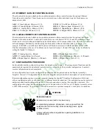
Nine common controller configurations have been stored in a built-in library that can be entered from the FCO LIB
function block at the STATION level. Simple changes can then be made to accommodate individual needs. As an
example, FCO101 Single Loop Controller includes the setpoint tracking feature but by simply disconnecting the TC
input to the SETPT function block, it becomes a fixed setpoint Single Loop Controller. These FCOs are fully
documented in Section 4.
FCO101
- Single Loop Controller w/ Tracking Setpoint
FCO102
- Single Loop Controller with Fixed Setpoint
FCO103
- External Set Controller with Tracking Local Setpoint
FCO104
- External Set Controller with Non-Tracking Local Setpoint
FCO105
- Ratio Set Controller with Operator Setpoint Limits
FCO106
- Single Loop Controller w/Operator Setpoint Limits
FCO107
- Dual Loop Controller
FCO121
- Cascade Loop Controller
FCO122
- Cascade Loop Controller with Operator Setpoint Limits
Unless otherwise specified on the order, FCO101 is installed at the factory. Use the following procedure to change
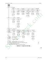
the factory configured option. Refer to Figure 2-1 Configuration Road Map to move to, and then through, the
selected FCO and to enter or edit parameter values.
1. Press the ENTER/EXIT CONF button. LOOP will appear on the alphanumeric display.
2. Rotate the Pulser Knob until STATION appears on alphanumeric display.
3. Press the STEP DOWN button to display FCO LIB.
4. Press the STEP DOWN button to display FCO in the lower display.
5. Press the STEP DOWN button until the desired FCO number appears in numeric display.
6. Rotate the Pulser Knob to display the desired FCO number in the upper display.
7. Press the STORE button to load the new FCO.
8. Edit the FCO as needed. In addition to the material in this section, refer to:
•
Section 3 Function Blocks for details about configurable parameters
•
Section 4 Factory Configured Options for FCO diagrams and parameters
•
Sections 6 and 7 for Modbus, LIL, or Ethernet mapping
•
Section 9 Operation for operating controls and displays
Where an FCO is not suitable, a complete configuration can be designed to suit individual needs. Section 4 can be
used as a guide for documenting a user-created or used-edited configuration. i|config, a PC-based Graphical
Configuration Utility, can be used to design, document, and save configurations as well as download them to the
controller, through either the configuration port or using a Modbus, LIL, or Ethernet network connection.
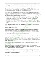
The above steps are illustrated in Figure 2-1 Configuration Road Map. The map also provides a broad overview of
the configuration procedure.
•
Press the ENTER CONF button to enter the configuration mode. Press the button again to exit configuration.
•
After entering the configuration mode, LOOP or STATION can be selected.
•
At the STATION level, a factory configured option can be loaded, station parameters can be configured,
security passwords can be entered, the clock can be set, communication parameters can be configured, and
inputs and outputs can be calibrated.
StockCheck.com
Содержание Moore 353
Страница 2: ...S t o c k C h e c k c o m ...
Страница 14: ...Contents UM353 1 xii March 2003 S t o c k C h e c k c o m ...
Страница 24: ...Introduction UM353 1 March 2003 1 10 S t o c k C h e c k c o m ...
Страница 152: ...LonWorks Communications UM353 1 March 2003 5 4 S t o c k C h e c k c o m ...
Страница 164: ...Network Communications UM353 1 6 12 March 2003 S t o c k C h e c k c o m ...
Страница 246: ...Operation UM353 1 March 2003 9 8 S t o c k C h e c k c o m ...
Страница 254: ...Controller and System Test UM353 1 March 2003 10 8 S t o c k C h e c k c o m ...
Страница 282: ...Circuit Description UM353 1 March 2003 13 4 S t o c k C h e c k c o m ...
Страница 298: ...Model Designation and Specifications UM353 1 March 2003 14 16 S t o c k C h e c k c o m ...
Страница 302: ...Abbreviations And Acronyms UM353 1 15 2 March 2003 S t o c k C h e c k c o m ...
Страница 304: ...Warranty UM353 1 W 2 March 2003 S t o c k C h e c k c o m ...


