


Model Designation and Specifications
UM353-1
March
2003
14-10
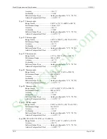
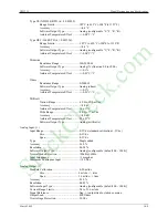
Digital Input: (1)
Logic “1” Range............................................15-30 Vdc
Logic “0” Range............................................0-1 Vdc
Overvoltage ...................................................+/-30
Vdc
Minimum Required ON Time .......................>Scan Time
Software
Output Type ...................................Digital
Isolation.........................................................100
Vdc
Universal Digital Inputs: (2)
Logic “1” Range............................................4-30 Vdc
Input Current .................................................<7 mA @ 30 V
Logic “0” Range............................................0-1 Vdc
Overvoltage ...................................................+/-30
Vdc
Frequency Range...........................................0 to 25,000 Hz.
Accuracy .......................................................0.03 % of reading
Minimum
Operating
Frequency ....................0.05 Hz.
Pulse
Width ...................................................20
µ
sec (minimum)
Signal Types..................................................Sine Square, Pulse, Triangle, or Contact Closure
(contacts
require external power)
Software
Output
Types: ...............................(a) Scaled Frequency: Analog
(b) Scaled Count: Analog
(c) Current Input State: Digital
Isolation.........................................................100
Vdc
Relay Outputs: (2)
Type ..............................................................Sealed (meets requirements of Division 2 applications)
Software Input Type......................................Digital
Contact
Configuration ...................................SPDT
Contact Rating...............................................5A @ 115 Vac; 2.5A @ 230 Vac (resistive load)
Minimum Current..........................................100 mA @ 10 mVdc or 150 mA @ 50 mVac
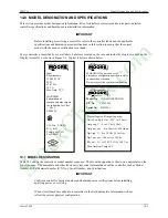
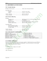
14.8 COMMUNICATION BOARDS
Communication boards plug into the Controller Board and provide digital communication as required by the
application. These boards provide digital communication for remote I/O and NETWORK communication for inter-
station/workstation/APACS networking. Three communication boards are designed to plug into the MPU controller
board: a LonWorks board and either a LIL Network board or an Ethernet board.
14.8.1 LonWorks Board
This board provides for additional I/O, remote from the Moore 353. The communication method allows various
configurations of analog and discrete signal types, both input and output, for use in control and/or sequencing
applications within the station.
14.8.2 LIL Network Board (Local Instrument Link
)
This board provides network communication, mapping station variables to the standard LIL channel/parameter
communication map. When this board is used, neither Modbus nor Ethernet communication are available. The
local configuration port under the faceplate is still available for configuration and diagnostic applications.
14.8.3 Ethernet Board
This board provides Ethernet communications. It function as a bi-directional Modbus-Ethernet converter. When
installed, neither LIL nor Modbus communications are available. The local configuration port under the faceplate is
still available for configuration and diagnostic applications.
StockCheck.com
Содержание Moore 353
Страница 2: ...S t o c k C h e c k c o m ...
Страница 14: ...Contents UM353 1 xii March 2003 S t o c k C h e c k c o m ...
Страница 24: ...Introduction UM353 1 March 2003 1 10 S t o c k C h e c k c o m ...
Страница 152: ...LonWorks Communications UM353 1 March 2003 5 4 S t o c k C h e c k c o m ...
Страница 164: ...Network Communications UM353 1 6 12 March 2003 S t o c k C h e c k c o m ...
Страница 246: ...Operation UM353 1 March 2003 9 8 S t o c k C h e c k c o m ...
Страница 254: ...Controller and System Test UM353 1 March 2003 10 8 S t o c k C h e c k c o m ...
Страница 282: ...Circuit Description UM353 1 March 2003 13 4 S t o c k C h e c k c o m ...
Страница 298: ...Model Designation and Specifications UM353 1 March 2003 14 16 S t o c k C h e c k c o m ...
Страница 302: ...Abbreviations And Acronyms UM353 1 15 2 March 2003 S t o c k C h e c k c o m ...
Страница 304: ...Warranty UM353 1 W 2 March 2003 S t o c k C h e c k c o m ...