Installation
UM353-1
March
2003
8-4
A
G
00327
a
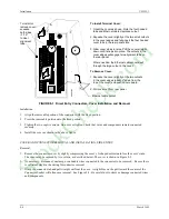
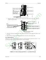
To Install Terminal Cover:
1. Orient the cover as shown. Note the four hooked
tabs and Ethernet cable clearance cutout.
2. Squeeze the cover slightly at the two small cutouts
in the cover edges and fully insert the four hooked
cover tabs in the rear panel slots.
3. Allow cover sides to relax. Pull the cover straight
down until it snaps into place. The cutouts in the
cover edges will engage two alignment tabs on
the rear panel.
Where needed, the Ethernet cable should exit
through the large cutout in the cover.
To Remove Cover:
1. Squeeze the cover slightly at the two cutouts
in the cover edges (about 2" down from the
top of the cover) and push cover upward.
2. Pull cover out from rear panel.
To install or
remove cover:
squeeze
both sides
~1/16"
to clear
alignment
tabs.
Ethernet cable cutout.
FIGURE 8-1 Direct Entry Connectors, Cover Installation and Removal
Installation
1. Align the removable portion of the connector with the fixed portion.
2. Press the removable portion onto the fixed portion.
3. Tighten the two captive screws. Do not over tighten. Check that wires and components remain connected
securely.
4. Install the cover as shown in the above figure.
COVER AND CONNECTOR REMOVAL AND INSTALLATION, SIDE ENTRY
Removal:
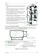
1. Remove the connector cover by slightly compressing the cover’s U-shaped extrusion to free the cover’s tabs.
The cover may be secured by two screws, as described below. The cover is shown in Figure 8-5.
2. As necessary, disconnect, unclamp, or unbundle wires connected to the connector to be removed. Be sure there
is sufficient slack in the wiring for connector removal.
3. Grasp the connector tab and pull straight out from the case. A slight bias on the pull toward the center of the
Connector Socket will often ease removal. See Figure 8-3. Be careful not to stress or damage connected wires
and components.
StockCheck.com
Содержание Moore 353
Страница 2: ...S t o c k C h e c k c o m ...
Страница 14: ...Contents UM353 1 xii March 2003 S t o c k C h e c k c o m ...
Страница 24: ...Introduction UM353 1 March 2003 1 10 S t o c k C h e c k c o m ...
Страница 152: ...LonWorks Communications UM353 1 March 2003 5 4 S t o c k C h e c k c o m ...
Страница 164: ...Network Communications UM353 1 6 12 March 2003 S t o c k C h e c k c o m ...
Страница 246: ...Operation UM353 1 March 2003 9 8 S t o c k C h e c k c o m ...
Страница 254: ...Controller and System Test UM353 1 March 2003 10 8 S t o c k C h e c k c o m ...
Страница 282: ...Circuit Description UM353 1 March 2003 13 4 S t o c k C h e c k c o m ...
Страница 298: ...Model Designation and Specifications UM353 1 March 2003 14 16 S t o c k C h e c k c o m ...
Страница 302: ...Abbreviations And Acronyms UM353 1 15 2 March 2003 S t o c k C h e c k c o m ...
Страница 304: ...Warranty UM353 1 W 2 March 2003 S t o c k C h e c k c o m ...


