Installing/Mounting
4.4 Connecting a CU240S DP or CU240S DP-F via PROFIBUS DP
Control Units CU240S
Operating Instructions, 07/2008 - FW 3.2, A5E00766042B AD
37
4.4
Connecting a CU240S DP or CU240S DP-F via PROFIBUS DP
Description
The function of the PROFIBUS DP interface is to provide a PROFIBUS DP-based link
between inverters of the SINAMICS G120 product range and higher-level automation
systems e.g. SIMATIC S7.
4.4.1
Connecting the PROFIBUS DP
Connecting the Inverter to the PROFIBUS DP network
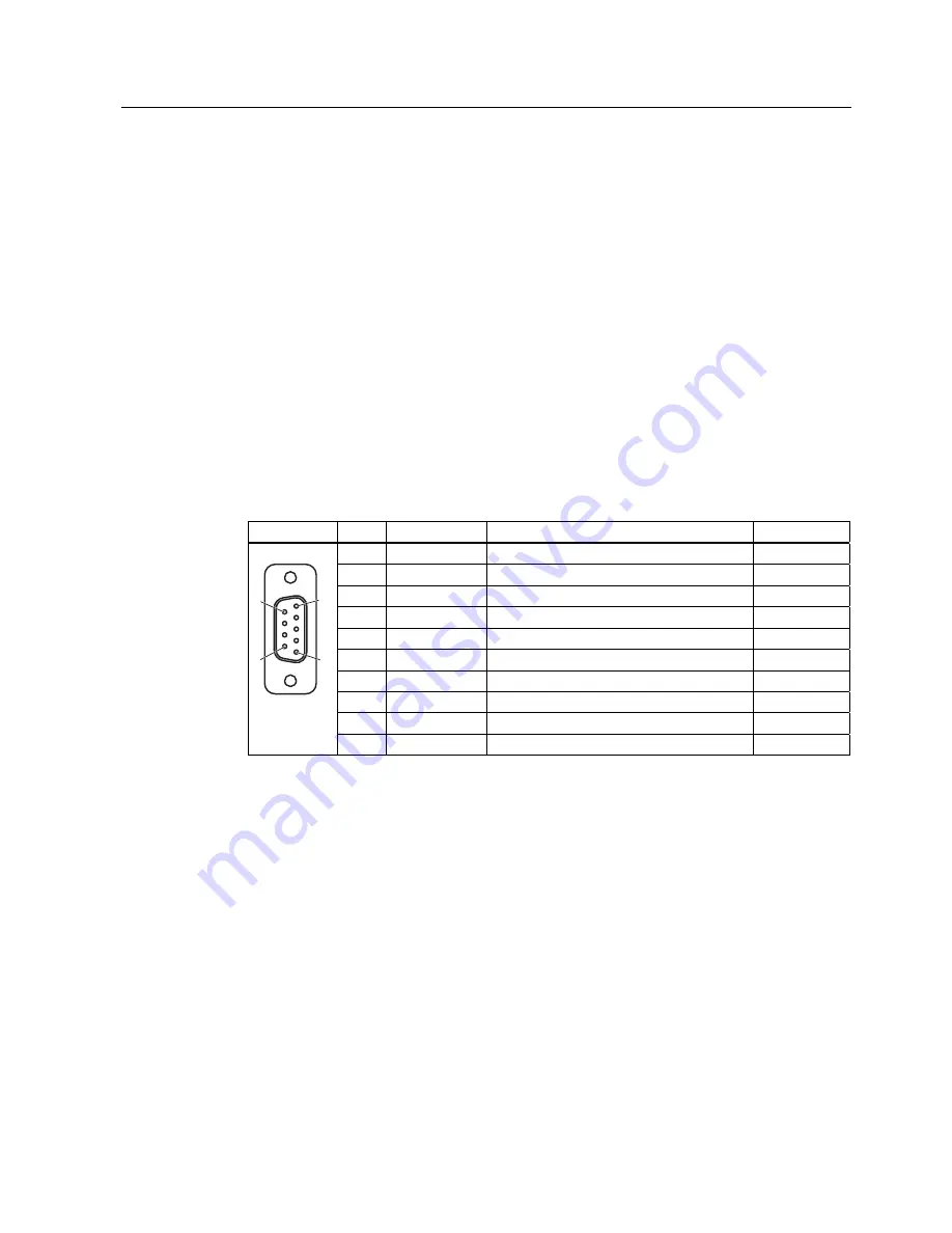
The inverter is to be connected to the PROFIBUS DP network via a sub-D socket on the
CU240S DP or CU240S DP-F. The pins of the socket are short-circuit-proof and isolated.
Table 4-4
PIN assignment of the 9-pin sub-D socket
Pin
Designation
Description
Range
1
Shield
Ground connection
2
U0V
Isolated and user supply reference
3
RxD/TxD-P
Receive/send data P (B/B')
RS485
4
CNTR-P
Control Signal
TTL
5
DGND
PROFIBUS data reference potential (C/C')
6
VP
Supply voltage positive
5 V ± 10 %
7
U24V
Isolated user 24 V @ 100 mA
8
RxD/TxD-N
Receive/send data N (A/A')
RS485
9
-
Not assigned
Case Cable shield
Cable shield
External 24 V supply
If the PROFIBUS DP interface is required to communicate with the Control Unit when the
Power Module mains power is not present, a 24 V supply must be connected to the Control
Unit terminals 31 (+ 24 V I
n
) and 32 (0 V I
n
).
Maximum cable length
The PROFIBUS system can handle up to 126 stations. To run all these stations the
PROFIBUS system is divided into segments. All segments have to be connected via
repeater. The maximum number of stations on any segment must not exceed 32.
The maximum cable lengths are dependent on the baud rate (transmission speed). The
maximum cable lengths specified in the table below can be guaranteed only with PROFIBUS
bus cables (for example, Siemens PROFIBUS bus cable, order number 6XV1830-0EH10).


