7SR210 & 7SR220 Installation Guide
Unrestricted ©2018 Siemens Protection Devices Limited
Page 21 of 36
Section 6: Data Comms Connections
6.1
Standard RS485 Connections
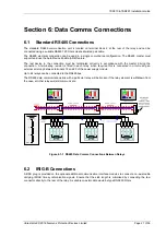
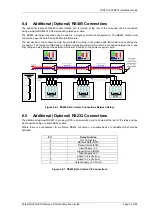
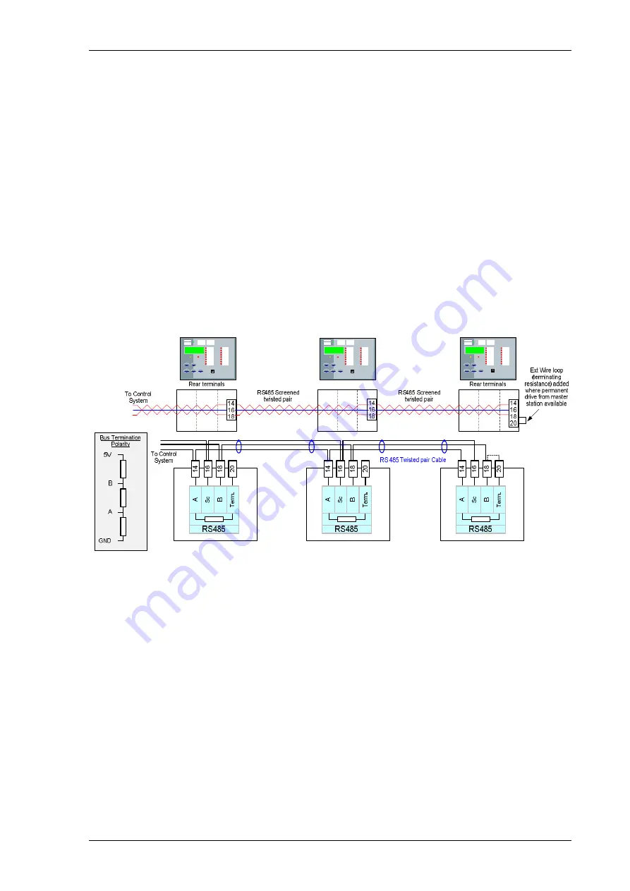
The standard RS485 communication port is located on terminal block 2 at the rear of the relay and can be
connected using a suitable RS485 120 Ohm screened twisted pair cable.
The RS485 electrical connection can be used in a single or multi-drop configuration. The RS485 master must
support and use the Auto Device Enable (ADE) feature.
The last device in the connection must be terminated correctly in accordance with the master driving the
connection. A terminating resistor is fitted in each relay, when required this is connected in circuit using an
external wire loop between terminals 18 and 20 of the power supply module.
Up to 64 relays can be connected to the RS485 bus.
The RS485 data communications link with a particular relay will be broken if the relay element is withdrawn from
the case, all other relays will still communicate.
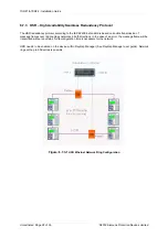
Figure 6.1-1 RS485 Data Comms Connections Between Relays
6.2
IRIG-B Connections
A BNC plug is provided on the optional additional communication interface modules to connect a co-axial cable
carrying IRIG-B time synchronisation signals. Ensure that the stub length is minimised by connecting the tee-
connector directly to the rear of the relay. A suitable co-axial cable would be type RG58 50 Ohms.
Содержание Argus 7SR21
Страница 1: ...Energy Management 7SR21 7SR22 Argus Overcurrent Relay Reyrolle Protection Devices ...
Страница 2: ......
Страница 4: ...Contents 7SR11 and 7SR12 Page 2 of 2 2018 Siemens Protection Devices Limited ...
Страница 116: ...7SR210 Instrumentation Guide Unrestricted Page 4 of 12 2018 Siemens Protection Devices Limited 1 Function Diagram ...
Страница 117: ...7SR210 Instrumentation Guide Unrestricted 2018 Siemens Protection Devices Limited Page 5 of 12 2 Menu Structure ...
Страница 129: ...7SR210 Settings Guide Unrestricted 2018 Siemens Protection Devices Limited Page 5 of 61 1 Function Diagram ...
Страница 130: ...7SR210 Settings Guide Unrestricted Page 6 of 61 2018 Siemens Protection Devices Limited 2 Menu Structure ...
Страница 185: ...7SR210 Settings Guide Unrestricted 2018 Siemens Protection Devices Limited Page 61 of 61 ...
Страница 189: ...7SR220 Instrumentation Guide Page 4 of 20 2017 Siemens Protection Devices Limited 1 Function Diagram ...
Страница 190: ...7SR220 Instrumentation Guide 2017 Siemens Protection Devices Limited Page 5 of 20 2 Menu Structure ...
Страница 194: ...7SR220 Instrumentation Guide 2017 Siemens Protection Devices Limited Page 9 of 20 Frequency 0 000Hz ...
Страница 211: ...7SR220 Settings Guide Unrestricted Page 6 of 107 2013 Siemens Protection Devices Limited 1 Function Diagram ...
Страница 277: ...7SR220 Settings Guide Unrestricted Page 72 of 107 2013 Siemens Protection Devices Limited ...
Страница 382: ...7SR220 Technical Manual Chapter 4 Page 2 of 96 2017 Siemens Protection Devices Limited ...
Страница 386: ...7SR220 Technical Manual Chapter 4 Page 6 of 96 2017 Siemens Protection Devices Limited ...
Страница 398: ...7SR220 Technical Manual Chapter 4 Page 18 of 96 2017 Siemens Protection Devices Limited ...
Страница 414: ...7SR220 Technical Manual Chapter 4 Page 34 of 96 2017 Siemens Protection Devices Limited ...
Страница 466: ...7SR220 Technical Manual Chapter 4 Page 86 of 96 2017 Siemens Protection Devices Limited ...
Страница 468: ...7SR220 Technical Manual Chapter 4 Page 88 of 96 2017 Siemens Protection Devices Limited ...
Страница 470: ...7SR220 Technical Manual Chapter 4 Page 90 of 96 2017 Siemens Protection Devices Limited ...
Страница 472: ...7SR220 Technical Manual Chapter 4 Page 92 of 96 2017 Siemens Protection Devices Limited ...
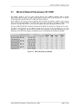
Страница 643: ...Unrestricted ...

