

7SR210 & 7SR220 Description of Operation
Unrestricted ©2018 Siemens Protection Devices Limited
Page 89 of 94
6.3
Data Storage
6.3.1
General
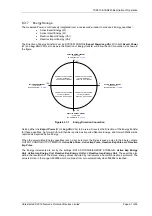
The relay stores three types of data records: relay event records, analogue/digital waveform records and fault
records. Data records are backed up in non-volatile memory and are permanently stored even in the event of loss
of auxiliary d.c. supply voltage.
6.3.2
Event Records
The event recorder feature allows the time tagging of any change of state (Event) in the relay. As an event
occurs, the actual event condition is logged as a record along with a time and date stamp to a resolution of 1
millisecond. There is capacity for a maximum of 5000 event records that can be stored in the relay and when the
event buffer is full any new record will over-write the oldest. Stored events can be erased using the DATA
STORAGE>
Clear Events
setting.
The following events are logged: -
Change of state of Binary outputs.
Change of state of Binary inputs.
Change of Settings and Settings Group.
Change of state of any of the control functions of the relay.
Protection element operation.
All events can be blocked or made available and uploaded over the data communications channel(s) and can be
displayed in the ‘Reydisp Evolution’ package in chronological order, allowing the sequence of events to be
viewed. Events are also made available spontaneously to an IEC 60870-5-103, Modbus RTU or DNP3.0
compliant control system. The function number and event number can also be changed. The events are selected
and edited using the Reydisp software tool.
6.3.3
Waveform Records.
Waveform records provide a trace of the instantaneous magnitude of each analogue input channel and the status
of each binary channel i.e. each binary input, binary output, virtual I/O and LED, against time for the duration of
the record. The values are recorded at every digital sampling point used by the relay software.
Each recorded analogue waveform displays an input identifier, minimum value, maximum value and the
instantaneous values at both cursor positions (user variable). Each binary waveform displays the input/output
number and the initiating condition(s) e.g. external input or protection element.
Triggering of waveform storage is configured from the ‘Settings > DATA STORAGE > WAVEFORM STORAGE’
menu. Triggering is automatically initiated from operation of any of the selected protection or control elements.
Waveform storage can also be triggered from the relay fascia, from a suitably programmed binary input or via the
data comms channel(s).
Waveforms are sampled at a rate of 32 samples per cycle.
The latest 10 records are stored; the most recent is waveform 1. Records are archived by the relay during
quiescent periods. The duration of each stored record is 1s, 2s, 5s or 10s. The user can also specify the
percentage of waveform storage prior to waveform triggering. When the waveform archive buffer is full (i.e. 10
records are stored) the triggering of a new waveform record causes the oldest record - waveform 10 – to be
overwritten.
Stored waveforms can be deleted from the relay fascia using the DATA STORAGE >
Clear Waveforms
setting or
via Reydisp.
Содержание Argus 7SR21
Страница 1: ...Energy Management 7SR21 7SR22 Argus Overcurrent Relay Reyrolle Protection Devices ...
Страница 2: ......
Страница 4: ...Contents 7SR11 and 7SR12 Page 2 of 2 2018 Siemens Protection Devices Limited ...
Страница 116: ...7SR210 Instrumentation Guide Unrestricted Page 4 of 12 2018 Siemens Protection Devices Limited 1 Function Diagram ...
Страница 117: ...7SR210 Instrumentation Guide Unrestricted 2018 Siemens Protection Devices Limited Page 5 of 12 2 Menu Structure ...
Страница 129: ...7SR210 Settings Guide Unrestricted 2018 Siemens Protection Devices Limited Page 5 of 61 1 Function Diagram ...
Страница 130: ...7SR210 Settings Guide Unrestricted Page 6 of 61 2018 Siemens Protection Devices Limited 2 Menu Structure ...
Страница 185: ...7SR210 Settings Guide Unrestricted 2018 Siemens Protection Devices Limited Page 61 of 61 ...
Страница 189: ...7SR220 Instrumentation Guide Page 4 of 20 2017 Siemens Protection Devices Limited 1 Function Diagram ...
Страница 190: ...7SR220 Instrumentation Guide 2017 Siemens Protection Devices Limited Page 5 of 20 2 Menu Structure ...
Страница 194: ...7SR220 Instrumentation Guide 2017 Siemens Protection Devices Limited Page 9 of 20 Frequency 0 000Hz ...
Страница 211: ...7SR220 Settings Guide Unrestricted Page 6 of 107 2013 Siemens Protection Devices Limited 1 Function Diagram ...
Страница 277: ...7SR220 Settings Guide Unrestricted Page 72 of 107 2013 Siemens Protection Devices Limited ...
Страница 382: ...7SR220 Technical Manual Chapter 4 Page 2 of 96 2017 Siemens Protection Devices Limited ...
Страница 386: ...7SR220 Technical Manual Chapter 4 Page 6 of 96 2017 Siemens Protection Devices Limited ...
Страница 398: ...7SR220 Technical Manual Chapter 4 Page 18 of 96 2017 Siemens Protection Devices Limited ...
Страница 414: ...7SR220 Technical Manual Chapter 4 Page 34 of 96 2017 Siemens Protection Devices Limited ...
Страница 466: ...7SR220 Technical Manual Chapter 4 Page 86 of 96 2017 Siemens Protection Devices Limited ...
Страница 468: ...7SR220 Technical Manual Chapter 4 Page 88 of 96 2017 Siemens Protection Devices Limited ...
Страница 470: ...7SR220 Technical Manual Chapter 4 Page 90 of 96 2017 Siemens Protection Devices Limited ...
Страница 472: ...7SR220 Technical Manual Chapter 4 Page 92 of 96 2017 Siemens Protection Devices Limited ...
Страница 643: ...Unrestricted ...