7SR210 & 7SR220 Commissioning & Maintenance Guide
© 2013 Siemens Protection Devices Limited
Page 5 of 82
List of Figures
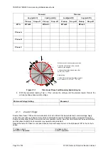
Figure 2.1-1 Directional Phase Fault Boundary System Angles
................................................... 16
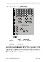
Figure 2.2-1 Phase Overcurrent
..................................................................................................... 17
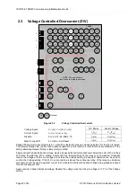
Figure 2.3-1 Voltage Controlled Overcurrent
................................................................................. 20
Figure 2.4-1 Cold Load
................................................................................................................... 22
Figure 2.4-2 Cold Load Logic diagram
........................................................................................... 23
Figure 2.1-1 Arc Flash Detection
.................................................................................................... 25
Figure 2.5-1 Directional Earth Fault Boundary System Angles
.................................................... 26
Figure 2.6-1 Derived Earth Fault
.................................................................................................... 27
Figure 2.7-1 Measured Earth Fault
................................................................................................. 31
Figure 2.8-1 Sensitive Earth Fault
.................................................................................................. 35
Figure 2.9-1 Restricted Earth Fault
................................................................................................ 39
Figure 2.10-1
Negative Phase Sequence Overcurrent
.............................................................. 41
Figure 2.11-1
Undercurrent
........................................................................................................ 44
Figure 2.12-1
Thermal Overload
................................................................................................ 46
Figure 2.13-1
Phase Under/Over Voltage
.................................................................................. 48
Figure 2.13-2
Vx Under/Over Voltage
........................................................................................ 51
Figure 2.13-3
NPS Overvoltage
.................................................................................................. 53
Figure 2.13-4
Neutral Overvoltage
............................................................................................. 55
Figure 2.13-5
Under/Over Frequency
........................................................................................ 57
Figure 2.11-1
Power
................................................................................................................... 59
Figure 2.12-1
Sensitive Power
................................................................................................... 61
Figure 2.13-1
Power Factor
........................................................................................................ 63
Figure 3.1-1 CB Fail
........................................................................................................................ 65
Figure 3.2-1 Voltage Transformer Supervision
.............................................................................. 67
Figure 3.3-1 Current Transformer Supervision
.............................................................................. 69
Figure 3.4-1 Broken Conductor
...................................................................................................... 71
Figure 3.5-1 Load Blinder (21)
........................................................................................................ 73
Figure 3.5-2 Load Blinder (21) Boundary Points
........................................................................... 74
Figure 3.6-1 Trip Circuit Supervision
............................................................................................. 77
Figure 3.7-1 Magnetising Inrush Detector
..................................................................................... 78
Figure 3.1-1 Magnetising Inrush Detector
..................................................................................... 79
Содержание Argus 7SR21
Страница 1: ...Energy Management 7SR21 7SR22 Argus Overcurrent Relay Reyrolle Protection Devices ...
Страница 2: ......
Страница 4: ...Contents 7SR11 and 7SR12 Page 2 of 2 2018 Siemens Protection Devices Limited ...
Страница 116: ...7SR210 Instrumentation Guide Unrestricted Page 4 of 12 2018 Siemens Protection Devices Limited 1 Function Diagram ...
Страница 117: ...7SR210 Instrumentation Guide Unrestricted 2018 Siemens Protection Devices Limited Page 5 of 12 2 Menu Structure ...
Страница 129: ...7SR210 Settings Guide Unrestricted 2018 Siemens Protection Devices Limited Page 5 of 61 1 Function Diagram ...
Страница 130: ...7SR210 Settings Guide Unrestricted Page 6 of 61 2018 Siemens Protection Devices Limited 2 Menu Structure ...
Страница 185: ...7SR210 Settings Guide Unrestricted 2018 Siemens Protection Devices Limited Page 61 of 61 ...
Страница 189: ...7SR220 Instrumentation Guide Page 4 of 20 2017 Siemens Protection Devices Limited 1 Function Diagram ...
Страница 190: ...7SR220 Instrumentation Guide 2017 Siemens Protection Devices Limited Page 5 of 20 2 Menu Structure ...
Страница 194: ...7SR220 Instrumentation Guide 2017 Siemens Protection Devices Limited Page 9 of 20 Frequency 0 000Hz ...
Страница 211: ...7SR220 Settings Guide Unrestricted Page 6 of 107 2013 Siemens Protection Devices Limited 1 Function Diagram ...
Страница 277: ...7SR220 Settings Guide Unrestricted Page 72 of 107 2013 Siemens Protection Devices Limited ...
Страница 382: ...7SR220 Technical Manual Chapter 4 Page 2 of 96 2017 Siemens Protection Devices Limited ...
Страница 386: ...7SR220 Technical Manual Chapter 4 Page 6 of 96 2017 Siemens Protection Devices Limited ...
Страница 398: ...7SR220 Technical Manual Chapter 4 Page 18 of 96 2017 Siemens Protection Devices Limited ...
Страница 414: ...7SR220 Technical Manual Chapter 4 Page 34 of 96 2017 Siemens Protection Devices Limited ...
Страница 466: ...7SR220 Technical Manual Chapter 4 Page 86 of 96 2017 Siemens Protection Devices Limited ...
Страница 468: ...7SR220 Technical Manual Chapter 4 Page 88 of 96 2017 Siemens Protection Devices Limited ...
Страница 470: ...7SR220 Technical Manual Chapter 4 Page 90 of 96 2017 Siemens Protection Devices Limited ...
Страница 472: ...7SR220 Technical Manual Chapter 4 Page 92 of 96 2017 Siemens Protection Devices Limited ...
Страница 643: ...Unrestricted ...

