


7SR210 & 7SR220 Installation Guide
Unrestricted Page 4 of 36
©2018 Siemens Protection Devices Limited
7.7 Typical Connection: 7SR22 Voltage Transformer Configurations for Check Synchronisation35
7.8 Voltage Transformer Configurations ................................................................................... 36
L
IST OF
F
IGURES
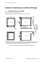
Figure 3.1-1 Overall Dimensions (mm) and panel Drilling for Size E6 Epsilon case .............................. 8
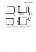
Figure 3.1-2 Overall Dimensions (mm) and Panel Drilling for Size E8 Epsilon Case ............................. 9
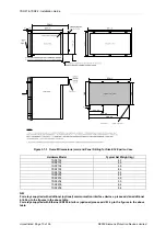
Figure 3.1-3 Overall Dimensions (mm) and Panel Drilling for Size E12 Epsilon Case ......................... 10
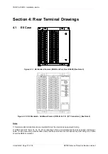
Figure 4.1-1 E6 Standard Comms (USB Front Port, Rear RS485) (See Note 2)................................. 12
Figure 4.1-2 E6 St Additional Comms (IRIG-B, 2 x F.O. (ST Connectors)) (See
Note 2) .......................................................................................................................... 12
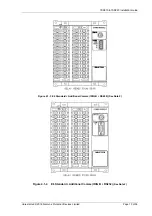
Figure 4.1-3 E6 St Additional Comms (IRIG B + RS485) (See Note 2) ................................. 13
Figure 4.1-4 E6 St Additional Comms (IRIG B + RS232) (See Note 2) ................................ 13
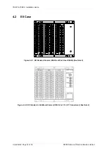
Figure 4.2-1 E8 Standard Comms (USB Front Port, Rear RS485) (See Note 2)................................. 14
Figure 4.2-2 E8 St Additional Comms (IRIG B, 2 x F.O. (ST Connectors)) (See
Note 2) .......................................................................................................................... 14
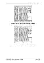
Figure 4.2-3 E8 St Additional Comms (IRIG B + RS485) (See Note 2) ................................. 15
Figure 4.2-4 E8 St Additional Comms (IRIG B + RS232) (See Note 2) ................................. 15
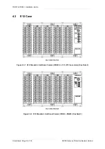
Figure 4.3-1 E12 St Additional Comms (IRIG B, 2 x F.O. (ST Connectors)) (See
Note 2) .......................................................................................................................... 16
Figure 4.3-2 E12 St Additional Comms (IRIG B + RS485) (See Note 2) ............................... 16
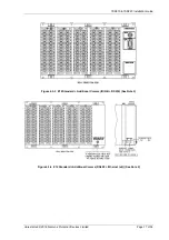
Figure 4.3-3 E12 St Additional Comms (IRIG B + RS232) (See Note 2) ............................... 17
Figure 4.3-4 E12 St Additional Comms (RS485 + Ethernet (x2)) (See Note 2) ..................... 17
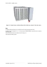
Figure 4.3-5 Standard Comms + Additional Ethernet Ports (RJ45 shown, Duplex LC Fibre
Optic similar) ................................................................................................................. 18
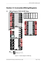
Figure 5.1-1 Connection Diagram for 7SR21 Relay ........................................................................... 19
Figure 5.2-1 Connection Diagram for 7SR22 Relay ........................................................................... 20
Figure 6.1-1 RS485 Data Comms Connections Between Relays ....................................................... 21
Figure 6.3-1 Data Comms to Multiple Devices Using 7SG24 and F.O. Star Network .......................... 22
Figure 6.3-2 Data Comms to Multiple Devices Using 7SG24 and F.O. Ring Network ......................... 22
Figure 6.4-1 RS485 Data Comms Connections Between Relays ....................................................... 23
Figure 6.5-1 RS232 Data Comms Pin Connections ........................................................................... 23
Figure 6.6-1 Ethernet connection for IEC 61850 (star connection) ..................................................... 24
Figure 6.6-2 Ethernet connection for IEC 61850 (ring connection) ..................................................... 24
Figure 6.7-1 EN100 Redundancy Availability ..................................................................................... 25
Figure 7.1-1 7SR22 Applied to Transformer Incomer ......................................................................... 29
Figure 7.2-1 7SR22 Applied to Transformer Incomer Including HV NVD Protection......................... 30
Figure 7.3-1 7SR22 Applied to Feeder Including NVD Protection....................................................... 31
Figure 7.4-1 7SR22 Applied to Feeder .............................................................................................. 32
Figure 7.5-1 7SR22 Applied to Feeder - No Zero Sequence Voltage Source ..................................... 33
Figure 7.6-1 7SR22 Applied to Feeder with Capacitor Cones Fitted ................................................... 34
Figure 7.7-1 7SR22 Applied to Check Synchronisation ...................................................................... 35
Figure 7.7-1 7SR22 VT Connections ................................................................................................. 36
Содержание Argus 7SR21
Страница 1: ...Energy Management 7SR21 7SR22 Argus Overcurrent Relay Reyrolle Protection Devices ...
Страница 2: ......
Страница 4: ...Contents 7SR11 and 7SR12 Page 2 of 2 2018 Siemens Protection Devices Limited ...
Страница 116: ...7SR210 Instrumentation Guide Unrestricted Page 4 of 12 2018 Siemens Protection Devices Limited 1 Function Diagram ...
Страница 117: ...7SR210 Instrumentation Guide Unrestricted 2018 Siemens Protection Devices Limited Page 5 of 12 2 Menu Structure ...
Страница 129: ...7SR210 Settings Guide Unrestricted 2018 Siemens Protection Devices Limited Page 5 of 61 1 Function Diagram ...
Страница 130: ...7SR210 Settings Guide Unrestricted Page 6 of 61 2018 Siemens Protection Devices Limited 2 Menu Structure ...
Страница 185: ...7SR210 Settings Guide Unrestricted 2018 Siemens Protection Devices Limited Page 61 of 61 ...
Страница 189: ...7SR220 Instrumentation Guide Page 4 of 20 2017 Siemens Protection Devices Limited 1 Function Diagram ...
Страница 190: ...7SR220 Instrumentation Guide 2017 Siemens Protection Devices Limited Page 5 of 20 2 Menu Structure ...
Страница 194: ...7SR220 Instrumentation Guide 2017 Siemens Protection Devices Limited Page 9 of 20 Frequency 0 000Hz ...
Страница 211: ...7SR220 Settings Guide Unrestricted Page 6 of 107 2013 Siemens Protection Devices Limited 1 Function Diagram ...
Страница 277: ...7SR220 Settings Guide Unrestricted Page 72 of 107 2013 Siemens Protection Devices Limited ...
Страница 382: ...7SR220 Technical Manual Chapter 4 Page 2 of 96 2017 Siemens Protection Devices Limited ...
Страница 386: ...7SR220 Technical Manual Chapter 4 Page 6 of 96 2017 Siemens Protection Devices Limited ...
Страница 398: ...7SR220 Technical Manual Chapter 4 Page 18 of 96 2017 Siemens Protection Devices Limited ...
Страница 414: ...7SR220 Technical Manual Chapter 4 Page 34 of 96 2017 Siemens Protection Devices Limited ...
Страница 466: ...7SR220 Technical Manual Chapter 4 Page 86 of 96 2017 Siemens Protection Devices Limited ...
Страница 468: ...7SR220 Technical Manual Chapter 4 Page 88 of 96 2017 Siemens Protection Devices Limited ...
Страница 470: ...7SR220 Technical Manual Chapter 4 Page 90 of 96 2017 Siemens Protection Devices Limited ...
Страница 472: ...7SR220 Technical Manual Chapter 4 Page 92 of 96 2017 Siemens Protection Devices Limited ...
Страница 643: ...Unrestricted ...