


7SR210 & 7SR220 Applications Guide
Page 30 of 48
©2018 Siemens Protection Devices Limited
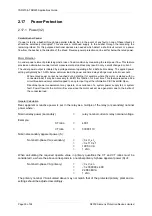
2.17 Power Protection
2.17.1 Power (32)
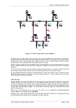
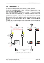
Parallel Busbar Feeder
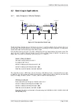
If power is fed to a busbar through two parallel infeeds, then in the event of any fault on one of these infeeds it
should be selectively interrupted. This ensures a continued supply to the busbar through the remaining the
remaining infeed. For this purpose directional devises are needed which detect a shortcircuit current or a power
flow from the busbar in the direction of the infeed. Reverse-power protection can be set far below the rated power.
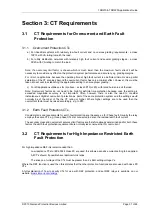
Motor Protection
An under power element protects against a loss of load condition by measuring the real power flow. This feature
provides an alternative to under current measurement as load loss may result in only a small change in current.
The under power output is initiated by a voltage element operating after a definite time delay. The applied power
setting will typically be 10-20% below minimum load, the power and time delay settings must take into account:
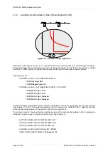
Where rated power cannot be reached during starting (for example where the motor is started with no
connected load) it may be necessary to inhibit this function for a set time. This feature requires a 52a
circuit breaker auxiliary contact mapped to an opto input to get the information CB Closed/CB Open.
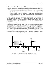
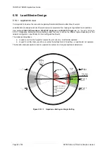
Directional power measurement may operate on occurrence of a system power supply fail or system
fault. Power flow into the motor will reverse since the motor will act as a generator due to the inertia of
the connected load.
General Calculation
Real, apparent or reactive power is set in the relay as a multiple of the relay (or secondary) nominal
power where: -
Nominal relay power (secondary)
=
relay nominal current x relay nominal voltage.
Example:
CT ratio
=
400:1
VT ratio
=
33000:110
Nominal secondary apparent power (S):
Nominal 3-phase VA (secondary)
=
√
3 x V
L
x I
L
=
√
3 x 110 x 1
=
190.53 VA
=
1 xSn
When calculating the required operate value in primary quantities the CT and VT ratios must be
considered i.e. where the above corresponds to a nominal primary 3-phase apparent power (S) of:
Nominal 3-phase VA (primary)
=
√
3 x V
L
x I
L
=
√
3 x 330000 x 400
=
22.863 MVA
=
1 xSn
The primary nominal VA calculated above may not match that of the protected primary plant and so
settings should be adjusted accordingly.
Содержание Argus 7SR21
Страница 1: ...Energy Management 7SR21 7SR22 Argus Overcurrent Relay Reyrolle Protection Devices ...
Страница 2: ......
Страница 4: ...Contents 7SR11 and 7SR12 Page 2 of 2 2018 Siemens Protection Devices Limited ...
Страница 116: ...7SR210 Instrumentation Guide Unrestricted Page 4 of 12 2018 Siemens Protection Devices Limited 1 Function Diagram ...
Страница 117: ...7SR210 Instrumentation Guide Unrestricted 2018 Siemens Protection Devices Limited Page 5 of 12 2 Menu Structure ...
Страница 129: ...7SR210 Settings Guide Unrestricted 2018 Siemens Protection Devices Limited Page 5 of 61 1 Function Diagram ...
Страница 130: ...7SR210 Settings Guide Unrestricted Page 6 of 61 2018 Siemens Protection Devices Limited 2 Menu Structure ...
Страница 185: ...7SR210 Settings Guide Unrestricted 2018 Siemens Protection Devices Limited Page 61 of 61 ...
Страница 189: ...7SR220 Instrumentation Guide Page 4 of 20 2017 Siemens Protection Devices Limited 1 Function Diagram ...
Страница 190: ...7SR220 Instrumentation Guide 2017 Siemens Protection Devices Limited Page 5 of 20 2 Menu Structure ...
Страница 194: ...7SR220 Instrumentation Guide 2017 Siemens Protection Devices Limited Page 9 of 20 Frequency 0 000Hz ...
Страница 211: ...7SR220 Settings Guide Unrestricted Page 6 of 107 2013 Siemens Protection Devices Limited 1 Function Diagram ...
Страница 277: ...7SR220 Settings Guide Unrestricted Page 72 of 107 2013 Siemens Protection Devices Limited ...
Страница 382: ...7SR220 Technical Manual Chapter 4 Page 2 of 96 2017 Siemens Protection Devices Limited ...
Страница 386: ...7SR220 Technical Manual Chapter 4 Page 6 of 96 2017 Siemens Protection Devices Limited ...
Страница 398: ...7SR220 Technical Manual Chapter 4 Page 18 of 96 2017 Siemens Protection Devices Limited ...
Страница 414: ...7SR220 Technical Manual Chapter 4 Page 34 of 96 2017 Siemens Protection Devices Limited ...
Страница 466: ...7SR220 Technical Manual Chapter 4 Page 86 of 96 2017 Siemens Protection Devices Limited ...
Страница 468: ...7SR220 Technical Manual Chapter 4 Page 88 of 96 2017 Siemens Protection Devices Limited ...
Страница 470: ...7SR220 Technical Manual Chapter 4 Page 90 of 96 2017 Siemens Protection Devices Limited ...
Страница 472: ...7SR220 Technical Manual Chapter 4 Page 92 of 96 2017 Siemens Protection Devices Limited ...
Страница 643: ...Unrestricted ...