
7SR210 Settings Guide
Unrestricted Page 52 of 61
© 2018 Siemens Protection Devices Limited
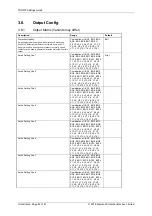
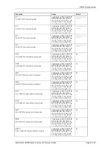
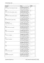
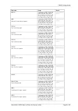
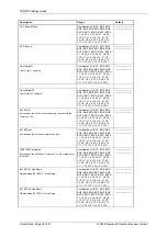
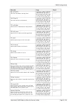
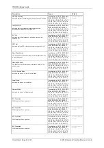
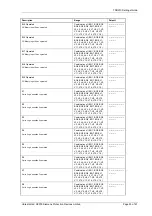
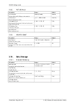
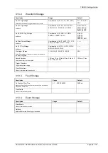
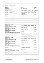
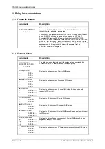
Description
Range
Default
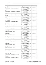
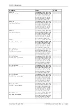
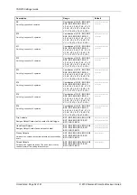
Hot Line Working
Indicates that Hot LineWorking functionality has been selected
Combination of ( BO1, BO2, BO3,
BO4, BO5, BO6, BO7, BO8, L1,
L2, L3, L4, L5, L6, L7, L8, V1, V2,
V3, V4, V5, V6, V7, V8, V9, V10,
V11, V12, V13, V14, V15, V16 )
----------------------
----------
Inst Prot'n Out
Indicates that the protection elements selected to be
Instantaneous elements are switched out
Combination of ( BO1, BO2, BO3,
BO4, BO5, BO6, BO7, BO8, L1,
L2, L3, L4, L5, L6, L7, L8, V1, V2,
V3, V4, V5, V6, V7, V8, V9, V10,
V11, V12, V13, V14, V15, V16 )
----------------------
----------
E/F Out
Indicates that the instantaneous protection elements are
switched out.
Combination of ( BO1, BO2, BO3,
BO4, BO5, BO6, BO7, BO8, L1,
L2, L3, L4, L5, L6, L7, L8, V1, V2,
V3, V4, V5, V6, V7, V8, V9, V10,
V11, V12, V13, V14, V15, V16 )
----------------------
----------
SEF Out
Indicates that the SEF protection elements are switched out
Combination of ( BO1, BO2, BO3,
BO4, BO5, BO6, BO7, BO8, L1,
L2, L3, L4, L5, L6, L7, L8, V1, V2,
V3, V4, V5, V6, V7, V8, V9, V10,
V11, V12, V13, V14, V15, V16 )
----------------------
----------
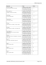
New Wave Stored
The waveform recorder has stored new information Note: this
is a pulsed output
Combination of ( BO1, BO2, BO3,
BO4, BO5, BO6, BO7, BO8, L1,
L2, L3, L4, L5, L6, L7, L8, V1, V2,
V3, V4, V5, V6, V7, V8, V9, V10,
V11, V12, V13, V14, V15, V16 )
----------------------
----------
New Fault Stored
The fault recorder has stored new information Note: this is a
pulsed output
Combination of ( BO1, BO2, BO3,
BO4, BO5, BO6, BO7, BO8, L1,
L2, L3, L4, L5, L6, L7, L8, V1, V2,
V3, V4, V5, V6, V7, V8, V9, V10,
V11, V12, V13, V14, V15, V16 )
----------------------
----------
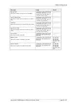
Out Of Service Mode
Indicates the relay is in Out Of Service Mode
Combination of ( BO1, BO2, BO3,
BO4, BO5, BO6, BO7, BO8, L1,
L2, L3, L4, L5, L6, L7, L8, V1, V2,
V3, V4, V5, V6, V7, V8, V9, V10,
V11, V12, V13, V14, V15, V16 )
----------------------
----------
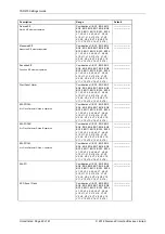
Local Mode
Indicates the relay is in Local Mode
Combination of ( BO1, BO2, BO3,
BO4, BO5, BO6, BO7, BO8, L1,
L2, L3, L4, L5, L6, L7, L8, V1, V2,
V3, V4, V5, V6, V7, V8, V9, V10,
V11, V12, V13, V14, V15, V16 )
----------------------
----------
Remote Mode
Indicates the relay is in Remote Mode
Combination of ( BO1, BO2, BO3,
BO4, BO5, BO6, BO7, BO8, L1,
L2, L3, L4, L5, L6, L7, L8, V1, V2,
V3, V4, V5, V6, V7, V8, V9, V10,
V11, V12, V13, V14, V15, V16 )
----------------------
----------
BI 1 Operated
DC Binary Input 1 has operated
Combination of ( BO1, BO2, BO3,
BO4, BO5, BO6, BO7, BO8, L1,
L2, L3, L4, L5, L6, L7, L8, V1, V2,
V3, V4, V5, V6, V7, V8, V9, V10,
V11, V12, V13, V14, V15, V16 )
----------------------
----------
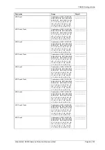
BI 2 Operated
DC Binary Input 2 has operated
Combination of ( BO1, BO2, BO3,
BO4, BO5, BO6, BO7, BO8, L1,
L2, L3, L4, L5, L6, L7, L8, V1, V2,
V3, V4, V5, V6, V7, V8, V9, V10,
V11, V12, V13, V14, V15, V16 )
----------------------
----------
BI 3 Operated
DC Binary Input 3 has operated
Combination of ( BO1, BO2, BO3,
BO4, BO5, BO6, BO7, BO8, L1,
L2, L3, L4, L5, L6, L7, L8, V1, V2,
V3, V4, V5, V6, V7, V8, V9, V10,
V11, V12, V13, V14, V15, V16 )
----------------------
----------
BI 4 Operated
DC Binary Input 4 has operated
Combination of ( BO1, BO2, BO3,
BO4, BO5, BO6, BO7, BO8, L1,
L2, L3, L4, L5, L6, L7, L8, V1, V2,
V3, V4, V5, V6, V7, V8, V9, V10,
V11, V12, V13, V14, V15, V16 )
----------------------
----------
Содержание Argus 7SR21
Страница 1: ...Energy Management 7SR21 7SR22 Argus Overcurrent Relay Reyrolle Protection Devices ...
Страница 2: ......
Страница 4: ...Contents 7SR11 and 7SR12 Page 2 of 2 2018 Siemens Protection Devices Limited ...
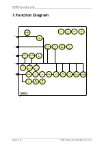
Страница 116: ...7SR210 Instrumentation Guide Unrestricted Page 4 of 12 2018 Siemens Protection Devices Limited 1 Function Diagram ...
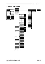
Страница 117: ...7SR210 Instrumentation Guide Unrestricted 2018 Siemens Protection Devices Limited Page 5 of 12 2 Menu Structure ...
Страница 129: ...7SR210 Settings Guide Unrestricted 2018 Siemens Protection Devices Limited Page 5 of 61 1 Function Diagram ...
Страница 130: ...7SR210 Settings Guide Unrestricted Page 6 of 61 2018 Siemens Protection Devices Limited 2 Menu Structure ...
Страница 185: ...7SR210 Settings Guide Unrestricted 2018 Siemens Protection Devices Limited Page 61 of 61 ...
Страница 189: ...7SR220 Instrumentation Guide Page 4 of 20 2017 Siemens Protection Devices Limited 1 Function Diagram ...
Страница 190: ...7SR220 Instrumentation Guide 2017 Siemens Protection Devices Limited Page 5 of 20 2 Menu Structure ...
Страница 194: ...7SR220 Instrumentation Guide 2017 Siemens Protection Devices Limited Page 9 of 20 Frequency 0 000Hz ...
Страница 211: ...7SR220 Settings Guide Unrestricted Page 6 of 107 2013 Siemens Protection Devices Limited 1 Function Diagram ...
Страница 277: ...7SR220 Settings Guide Unrestricted Page 72 of 107 2013 Siemens Protection Devices Limited ...
Страница 382: ...7SR220 Technical Manual Chapter 4 Page 2 of 96 2017 Siemens Protection Devices Limited ...
Страница 386: ...7SR220 Technical Manual Chapter 4 Page 6 of 96 2017 Siemens Protection Devices Limited ...
Страница 398: ...7SR220 Technical Manual Chapter 4 Page 18 of 96 2017 Siemens Protection Devices Limited ...
Страница 414: ...7SR220 Technical Manual Chapter 4 Page 34 of 96 2017 Siemens Protection Devices Limited ...
Страница 466: ...7SR220 Technical Manual Chapter 4 Page 86 of 96 2017 Siemens Protection Devices Limited ...
Страница 468: ...7SR220 Technical Manual Chapter 4 Page 88 of 96 2017 Siemens Protection Devices Limited ...
Страница 470: ...7SR220 Technical Manual Chapter 4 Page 90 of 96 2017 Siemens Protection Devices Limited ...
Страница 472: ...7SR220 Technical Manual Chapter 4 Page 92 of 96 2017 Siemens Protection Devices Limited ...
Страница 643: ...Unrestricted ...