7SR210 & 7SR220 Description of Operation
Unrestricted Page 16 of 94
©2018 Siemens Protection Devices Limited
2.2
Case
The relays are housed in cases designed to fit directly into standard panel racks. The three case options have
widths of 156 mm (E6), 208 mm (E8) and 304 mm (E12), with a height of 177 mm (4U). The required panel depth
(with wiring clearance) is 242 mm. An additional 75 mm depth clearance should be allowed to accommodate the
bending radius of fibre optic data communications cables if fitted. Relays with IEC 61850 communications option
require a depth of 261.5 mm to allow for the communication module and a clearance from devices fitted below the
relay of 75 mm to accommodate fitment of the Ethernet cables.
The complete relay assembly is withdrawable from the front of the case. Contacts in the case ensure that the CT
circuits remain short-circuited when the relay is removed. For the IEC 61850 variant options the rear retaining
screw must be re-fitted following re-insertion to ensure relay performance claims.
The rear terminal blocks comprise M4 female terminals for wire connections. Each terminal can accept two 4 mm
crimps. Located at the top rear of the case is a screw-clamp earthing point, this must be connected to the main
panel earth.
2.3
Front Cover
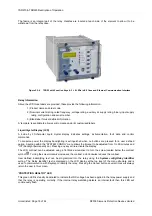
With the transparent front cover in place the user only has access to the
▼
and
TEST/RESET
►
buttons, via blue
push buttons, allowing all areas of the menu system to be viewed, but preventing setting changes and control
actions. The only ‘action’ that is permitted is to reset the Fault Data display, latched binary outputs and LEDs by
using the
TEST/RESET
4
button. The front cover is used to secure the relay assembly in the case.
2.4
Power Supply Unit (PSU)
The relay PSU can be directly connected to any substation dc system rated from 24 V dc to 250 V dc / 100 V ac
to 230 V ac.
In the event of the station battery voltage level falling below the relay minimum operating level, the PSU will
automatically switch itself off and latch out – this prevents any PSU overload conditions occurring. The PSU is
reset by switching the auxiliary supply off and on.
Typically the PSU is connected to the auxiliary supply via an external HRC fuse rated at 6A (BS88/IEC60259).
Isolation links may also be installed in accordance with user requirements.
2.5
Operator Interface/ Fascia
The operator interface is designed to provide a user-friendly method of controlling, entering settings and retrieving
data from the relay.
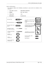
The warning and information labels on the relay fascia provide the following information: -
Dielectric Test Voltage 2kV
Impulse Test Above 5kV
Caution: Risk of Electric Shock
Caution: Refer to Equipment Documentation
Содержание Argus 7SR21
Страница 1: ...Energy Management 7SR21 7SR22 Argus Overcurrent Relay Reyrolle Protection Devices ...
Страница 2: ......
Страница 4: ...Contents 7SR11 and 7SR12 Page 2 of 2 2018 Siemens Protection Devices Limited ...
Страница 116: ...7SR210 Instrumentation Guide Unrestricted Page 4 of 12 2018 Siemens Protection Devices Limited 1 Function Diagram ...
Страница 117: ...7SR210 Instrumentation Guide Unrestricted 2018 Siemens Protection Devices Limited Page 5 of 12 2 Menu Structure ...
Страница 129: ...7SR210 Settings Guide Unrestricted 2018 Siemens Protection Devices Limited Page 5 of 61 1 Function Diagram ...
Страница 130: ...7SR210 Settings Guide Unrestricted Page 6 of 61 2018 Siemens Protection Devices Limited 2 Menu Structure ...
Страница 185: ...7SR210 Settings Guide Unrestricted 2018 Siemens Protection Devices Limited Page 61 of 61 ...
Страница 189: ...7SR220 Instrumentation Guide Page 4 of 20 2017 Siemens Protection Devices Limited 1 Function Diagram ...
Страница 190: ...7SR220 Instrumentation Guide 2017 Siemens Protection Devices Limited Page 5 of 20 2 Menu Structure ...
Страница 194: ...7SR220 Instrumentation Guide 2017 Siemens Protection Devices Limited Page 9 of 20 Frequency 0 000Hz ...
Страница 211: ...7SR220 Settings Guide Unrestricted Page 6 of 107 2013 Siemens Protection Devices Limited 1 Function Diagram ...
Страница 277: ...7SR220 Settings Guide Unrestricted Page 72 of 107 2013 Siemens Protection Devices Limited ...
Страница 382: ...7SR220 Technical Manual Chapter 4 Page 2 of 96 2017 Siemens Protection Devices Limited ...
Страница 386: ...7SR220 Technical Manual Chapter 4 Page 6 of 96 2017 Siemens Protection Devices Limited ...
Страница 398: ...7SR220 Technical Manual Chapter 4 Page 18 of 96 2017 Siemens Protection Devices Limited ...
Страница 414: ...7SR220 Technical Manual Chapter 4 Page 34 of 96 2017 Siemens Protection Devices Limited ...
Страница 466: ...7SR220 Technical Manual Chapter 4 Page 86 of 96 2017 Siemens Protection Devices Limited ...
Страница 468: ...7SR220 Technical Manual Chapter 4 Page 88 of 96 2017 Siemens Protection Devices Limited ...
Страница 470: ...7SR220 Technical Manual Chapter 4 Page 90 of 96 2017 Siemens Protection Devices Limited ...
Страница 472: ...7SR220 Technical Manual Chapter 4 Page 92 of 96 2017 Siemens Protection Devices Limited ...
Страница 643: ...Unrestricted ...

