


7SR210 & 7SR220 Commissioning & Maintenance Guide
© 2013 Siemens Protection Devices Limited
Page 53 of 82
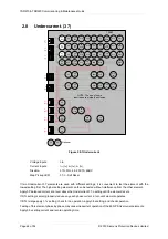
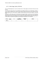
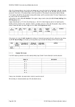
2.10.4 NPS Overvoltage (47)
7SR22
46
BC
46
NPS
(x2)
37
(x2)
49
50
BF
V
L1
(V
A
)
V
L2
(V
B
)
V
L3
(V
C
)
V
4
(V
X
)
I
L1
(I
A
)
81
HBL
2
37
(x2)
49
50
BF
I
L2
(I
B
)
81
HBL
2
37
(x2)
49
50
BF
I
L3
(I
C
)
81
HBL
2
60
CTS
I
4
(I
G
)
I
5
(I
SEF
)
74
TCS
NOTE: The use of some
functions are mutually exclusive
67/
50
(x4)
67/
51
(x4)
67/
50N
(x4)
67/
50
(x4)
67/
50
(x4)
67/
51
(x4)
67/
51
(x4)
67/
51N
(x4)
67/
50G
(x4)
67/
51G
(x4)
67/
50S
(x4)
67/
51S
(x4)
64
H
27
59
27
59
(x4)
27
59
(x4)
27
59
(x4)
47
(x2)
81
(x6)
79
Optional
59N
(x2)
81
HBL
2N
60
VTS
51V
51V
51V
37G
(x2)
37S
(x2)
51c
60
CTS-
I
60
CTS-
I
60
CTS-
I
37
50
BF
37
50
BF
25
50
AFD
50
AFD
50
AFD
51c
51c
51c
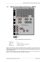
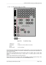
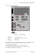
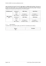
Figure 2.10-3
NPS Overvoltage
Voltage Inputs:
V
L1
(V
A
), V
L2
(V
B
), V
L3
(V
C
)
Current Inputs:
n/a apply zero current to stabilize other functions
Disable:
27/59, 59N, 60VTS
Map Pickup LED:.
47-n - Self Reset
Where two NPS elements are being used with different settings, it is convenient to test the elements with the
highest settings first. The elements with lower settings can then be tested without disabling the lower settings.
NPS Overvoltage can be tested using a normal 3P balanced source. Two phase voltage connections should be
reversed so that the applied balanced 3P voltage is Negative Phase Sequence.
If the 47-n delay is small, gradually increased the applied balanced 3P voltage until element operates.
If DTL is large apply 0.9x setting, check for no operation, apply 1.1x setting, and check operation.
Apply 2x setting current if possible and record operating time.
Содержание Argus 7SR21
Страница 1: ...Energy Management 7SR21 7SR22 Argus Overcurrent Relay Reyrolle Protection Devices ...
Страница 2: ......
Страница 4: ...Contents 7SR11 and 7SR12 Page 2 of 2 2018 Siemens Protection Devices Limited ...
Страница 116: ...7SR210 Instrumentation Guide Unrestricted Page 4 of 12 2018 Siemens Protection Devices Limited 1 Function Diagram ...
Страница 117: ...7SR210 Instrumentation Guide Unrestricted 2018 Siemens Protection Devices Limited Page 5 of 12 2 Menu Structure ...
Страница 129: ...7SR210 Settings Guide Unrestricted 2018 Siemens Protection Devices Limited Page 5 of 61 1 Function Diagram ...
Страница 130: ...7SR210 Settings Guide Unrestricted Page 6 of 61 2018 Siemens Protection Devices Limited 2 Menu Structure ...
Страница 185: ...7SR210 Settings Guide Unrestricted 2018 Siemens Protection Devices Limited Page 61 of 61 ...
Страница 189: ...7SR220 Instrumentation Guide Page 4 of 20 2017 Siemens Protection Devices Limited 1 Function Diagram ...
Страница 190: ...7SR220 Instrumentation Guide 2017 Siemens Protection Devices Limited Page 5 of 20 2 Menu Structure ...
Страница 194: ...7SR220 Instrumentation Guide 2017 Siemens Protection Devices Limited Page 9 of 20 Frequency 0 000Hz ...
Страница 211: ...7SR220 Settings Guide Unrestricted Page 6 of 107 2013 Siemens Protection Devices Limited 1 Function Diagram ...
Страница 277: ...7SR220 Settings Guide Unrestricted Page 72 of 107 2013 Siemens Protection Devices Limited ...
Страница 382: ...7SR220 Technical Manual Chapter 4 Page 2 of 96 2017 Siemens Protection Devices Limited ...
Страница 386: ...7SR220 Technical Manual Chapter 4 Page 6 of 96 2017 Siemens Protection Devices Limited ...
Страница 398: ...7SR220 Technical Manual Chapter 4 Page 18 of 96 2017 Siemens Protection Devices Limited ...
Страница 414: ...7SR220 Technical Manual Chapter 4 Page 34 of 96 2017 Siemens Protection Devices Limited ...
Страница 466: ...7SR220 Technical Manual Chapter 4 Page 86 of 96 2017 Siemens Protection Devices Limited ...
Страница 468: ...7SR220 Technical Manual Chapter 4 Page 88 of 96 2017 Siemens Protection Devices Limited ...
Страница 470: ...7SR220 Technical Manual Chapter 4 Page 90 of 96 2017 Siemens Protection Devices Limited ...
Страница 472: ...7SR220 Technical Manual Chapter 4 Page 92 of 96 2017 Siemens Protection Devices Limited ...
Страница 643: ...Unrestricted ...