


Operating Instructions
Chapter 5
ICR845-2
Electrical installation
8012377/0000/2008-01-30
©
SICK AG · Division Auto Ident · Germany · All rights reserved
31
5
Electrical installation
5.1
Overview of the installation sequence
Important
Electrical installation should only be carried out by qualified staff.
The following list provides an overview of a typical installation sequence:
Connecting the ICR845-2 to connection module CDB620 or CDM420
Wiring the data and function interfaces of the ICR845-2 in the connection module
Connecting the Ethernet interface on the ICR845-2 to the PC for image output and con-
figuration (recommended).
– Alternatively without image output: Connect the PCto the serial auxiliary interface in
the connection module
Optional: Connecting the external illumination to the connection module
Connecting the power supply to the connection module
Once electrical installation has been completed, the ICR845-2 is started up and configured
(see
Chapter 6 Startup and configuration, Page 47
).
5.2
Electrical installation preparations
The following general requirements should be observed for electrical installation:
Supply voltage 15 to 30 V DC (functional extra-low voltage in accordance with IEC 364-
4-41 (VDE 0100 Part 410)), power output at least 15 W, provided e.g. via power pack
by the customer.
Connecting the ICR845-2:
– Via connection module CDB620 or CDM420
– or –
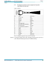
– If wiring without a SICK connection module use the cable no. 6010137 with 15-pin
D-Sub HD plug and open end to connect the ICR845-2.
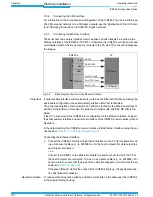
Fig. 5-1:
Block diagram for startup and configuration
Cable no. 2014054
PC/Laptop
CDB620/CDM420
RS 232
Cable no. 6026084 (crossover)
Configuration
Diagnosis
Image visualisation
24 V DC
RS 232 cable
alternatively to Ether-
net cable if no image
transfer is required
Ethernet
Configuration
Configuration/Image transfer
AUX


