


Chapter 10
Operating Instructions
ICR845-2 Image Code Reader
180
©
SICK AG · Division Auto Ident · Germany · All rights reserved
8012377/ 0000/ 2008-01-30
Appendix
Tab. 8-9:
Troubleshooting: Errors when using the image transfer via the
Ethernet interface .......................................................................................... 118
Tab. 9-1:
Technical specifcations of ICR845-2 ............................................................ 121
Tab. 9-2:
Mid Range: Suitable bar code lengths at focus position (distance
115 mm (4.53 in), field of view 44 mm x 28 mm (1.78 in x 1.1 in)).......... 122
Tab. 9-3:
Reading conditions for specification diagram.............................................. 124
Tab. 10-1:
System messages of the ICR845-2............................................................... 135
Tab. 10-2:
Default settings in CLV-Setup (extract)......................................................... 139
Tab. 10-3:
Functions of the CLV-Setup configuration software (overview) .................. 142
Tab. 10-4:
Formulas for calculating the code length of a bar code.............................. 148
Tab. 10-5:
Overview: Functions for the code comparison ............................................. 149
Tab. 10-6:
Teach-in modes for match code 1 ................................................................ 150
Tab. 10-7:
Communication parameter settings for the terminal/ PC for
the auxiliary inpute......................................................................................... 162
Tab. 10-8:
ECommunication parameter settings for the SICK Hand-held
Scanner from the IT 38xx/ 46xx/ 48xx/ 58xx series...................................... 162
Tab. 10-9:
Versions of the ICR845-2............................................................................... 164
Tab. 10-10: In stock accessories: Holder.......................................................................... 164
Tab. 10-11: In stock accessories: CDB620/ CDM420 Connection Modules.................. 165
Tab. 10-12: In stock accessories: Extensions for CDB620/ CDM420
Connection Modules ...................................................................................... 166
Tab. 10-13: In stock accessories: Cables and plug-in connections ................................ 167
Tab. 10-14: In stock accessories: Incremental encoder.................................................. 168
Tab. 10-15: In stock accessories: Opto-coupler ............................................................... 168
Tab. 10-16: Supplementary documentation..................................................................... 171
Figures
Fig. 2-1:
Outlet opening of the LED radiation at the ICR845-2.....................................11
Fig. 2-2:
Black-yellow signed warning labels found on the ICR845-2 ..........................11
Fig. 3-1:
Design of the ICR845-2 ....................................................................................14
Fig. 3-2:
ICR845-2: Direct marking methods for 2D codes...........................................17
Fig. 3-3:
Block diagram: functions of the ICR845-2 ......................................................18
Fig. 3-4:
Field of view of the ICR845-2 in the focus position (Mid Range)...................18
Fig. 3-5:
LEDs ...................................................................................................................20
Fig. 4-1:
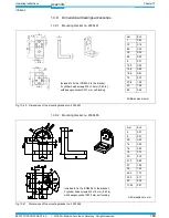
Installation accessories ....................................................................................24
Fig. 4-2:
Example: Fixing the ICR845-2 with the mounting bracket no. 2025491 .....24
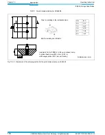
Fig. 4-3:
ICR845-2: Allocation of the field of view to the code .....................................25
Fig. 4-4:
Definition of the reading distance and the field of view.................................26
Fig. 4-5:
Reading angle that can occurs between the field of view and the code.......26
Fig. 4-6:
Avoiding surface reflection: Angle between emitting light and code
(tilted away from the plumb line) .....................................................................27
Fig. 4-7:
Count direction of the code position CP for bar codes along the
reading window..................................................................................................28
Fig. 4-8:
Installation example for the external reading pulse sensor ...........................30
Fig. 5-1:
Block diagram for startup and configuration ..................................................31
Fig. 5-2:
Block diagram: Connection of the ICR845-2 to the CDB620 or
CDM420 Connection Module...........................................................................34
Fig. 5-3:
Connecting the serial host interface................................................................38
Fig. 5-4:
Connecting the serial auxiliary interface .........................................................39
Fig. 5-5:
Block diagram: Function of the Ethernet interface.........................................40
Fig. 5-6:
Connecting the "Sensor 1" switching input .....................................................41
Fig. 5-7:
Connecting the "Sensor 2" switching input .....................................................41
Fig. 5-8:
Connecting the "Result 1" switching output for triggering an
external illumination .........................................................................................42
Fig. 5-9:
Connecting the "Result 1" switching output for indicating the result status
when the load (e.g. PLC) is directly connected, using a series resistor.........43


