


Operating Instructions
Chapter 5
ICR845-2
Electrical installation
8012377/0000/2008-01-30
©
SICK AG · Division Auto Ident · Germany · All rights reserved
41
5.5.6
Connecting the switching inputs
If a reading process is to be triggered on the ICR845-2 by an external sensor, the reading
pulse sensor must be connected to the "Sensor 1" switching input. The trigger type is select-
ed in the default setting of the ICR845-2.
Important
An external pulse is not required for "Percentage Evaluation" mode.
The "Sensor 2" switching input has the following function, among others:
Incremental encoder input
Reading pulse generator for reading pulse end
Trigger source for teach-in of match code 1/activation of code comparison
Connect the switching inputs depending on application.
The characteristics for "Sensor 1" and "Sensor 2" are identical.
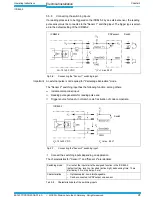
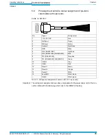
Fig. 5-6:
Connecting the "Sensor 1" switching input
PNP sensor
Switch
V
S
= 15 to 30 V DC
* ) V
in
= max. 28 V!
ICR845-2
V
in
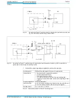
Fig. 5-7:
Connecting the "Sensor 2" switching input
Switch
ICR845-2
V
in
V
in
= max. 28 V!
V
S
= 15 to 30 V DC
Switching mode
Current at the input starts the assigned function in the ICR845-2.
(default setting: level: not inverted (active high), debouncing time: 10 ms,
start delay: 0 ms, stop delay: 0 ms)
Characteristics
– Optodecoupled, non-interchangeable
– Can be connected to PNP output on a sensor
Tab. 5-8: Characteristic data of the switching inputs