


16-5 PC monitor screen ................................................................................................................ 16-19
Chapter 17: Setting the Input/Output Conditions ................................... 17-1 to 17-24
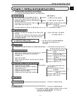
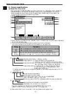
17-1 Outline ..................................................................................................................................... 17-1
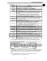
[1] When you want to select "PA USB" on the "MEAS INP I/F"line .............. 17-1
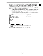
[2] When you want to select the "CCD-TRIG" on the "MEAS INP I/F" line ................................... 17-3
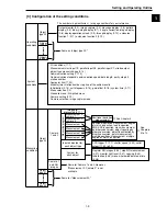
17-2 Measurement start input and result output settings ................................................................. 17-4
(1) Measurement start input = parallel, object type change = parallel, result output =
parallel ................................................................................................................................ 17-5
(2) Measurement start input = parallel, object type change = parallel, result output =
computer Iink/parallel .......................................................................................................... 17-6
(3) Measurement start input = parallel, object type change = parallel, result output =
general purpose serial/parallel ............................................................................................ 17-7
(4) Measurement start input = general-purpose serial, object type change =
general-purpose serial, result output = general-purpose serial/parallel .............................. 17-8
(5) Measurement start input = CCD trigger, start sampling = parallel, object type
change = parallel, result output = parallel ............................................................................ 17-9
(6) Measurement start input = CCD trigger, start sampling = parallel, object type
change = parallel, result output = computer link/parallel .................................................. 17-10
(7) Measurement start input = CCD trigger, start sampling = parallel, object type
change = parallel, result output = general purpose serial/parallel ...................................... 17-11
(8) Measurement start input = CCD trigger, start sampling, object type change =
general purpose serial, result output = general purpose serial/parallel ............................ 17-12
(9) Measurement start input = CCD trigger, start sampling = auto, object type change,
result output = parallel ...................................................................................................... 17-13
(10) Measurement start input = CCD trigger, start sampling = auto, object type
change = general purpose serial, result output = general purpose serial/parallel ............. 17-15
17-3 CCD trigger ............................................................................................................................ 17-17
[1] Outline .................................................................................................................................... 17-17
[2] Setting procedure ................................................................................................................... 17-17
17-4 Setting for serial communications .......................................................................................... 17-19
17-5 Computer link ......................................................................................................................... 17-20
17-6 Output block assignment (Computer link output and general purpose serial output) ............ 17-21
[1] Data in specified blocks ......................................................................................................... 17-21
(1) In the case of a computer link .......................................................................................... 17-21
(2) When the measurement is started by a CCD trigger or a parallel I/F signal and
the results are output by a general purpose serial I/F signal ............................................. 17-22
[2] Setting (operating) procedure ................................................................................................ 17-22
17-7 Setting the data output ........................................................................................................... 17-23
(1) Select "ANY" for the serial output ..................................................................................... 17-23
(2) Select "YES" or "NO" for output data ............................................................................... 17-23
Chapter 18: Communication (General Purpose Serial Interface) .......... 18-1 to 18-17
18-1 List of processing functions ..................................................................................................... 18-1
18-2 Data flow .................................................................................................................................. 18-3
[1] Measurement execution 1: Command codes 10, 11, or 12 ..................................................... 18-3
[2] Measurement execution 2: Response processing for command 11 ........................................ 18-3
[3] Measurement execution 3: Command 14 ................................................................................ 18-4
[4] Processing other than measurement execution processing .................................................... 18-4


