


16-4
PC Function
16
Continued from the previous
page
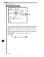
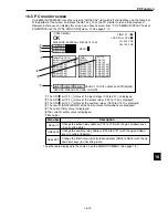
Ladder circuit
cursor
2
1
3
5
4
[PAGE0]
INPUT0
LOGIC
INPUT1
LOGIC
INPUT2
LOGIC
INPUT3
LOGIC
1
0
2
3
4
5
6
7
OUT
[OUTPUT COND]
1
PAGE NO.
0(0~4) NO YES
2
SET POSITION
MOVE
3
INPUT SIGNAL
REGISTER NO.0(0~7)
MATCH M0(0~1) CRD-X0(0~1) CRD-Y0(0~1)
DEV-x0(0~1) DEV-y0(0~1) ANGL-B
CALC N00(0~15) AUX.RLY-C000(0~127)
4
LOGIC SYMBOL
DEL
5
OUTPUT SIGNAL AUX-RLY C000(0~127)
OPS-MENU RETURN LOCK
0M0
0
1
2
3
4
5
6
7
OUT
[PAGE0]
INPUT0
LOGIC
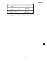
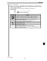
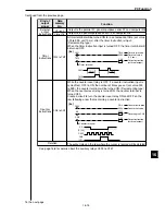
Logic symbol
Function
Deletes a contact on the cursor. (Contacts after the deleted contact will not be
brought forward.)
Note: This symbol cannot be used on the first row.
Deletes the contact on the cursor. (Contacts after the deleted contact will be
brought forward.)
When a contact exists only on the first row, if the contact is deleted, also the
output relay will be deleted.
a contact on a series circuit (ON, when the evaluation result is OK)
b contact on a series circuit (OFF, when the evaluation result is OK)
Used to create an OR circuit.
Used to create an OR circuit
DEL
To the next page
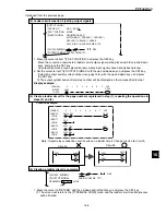
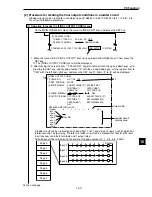
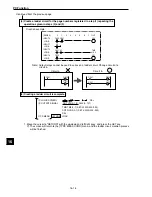
(2) Ladder circuit creation 1 (setting input signals)
1. Move the cursor to item "
2
SET POSITION" with the up and down keys, and press the SET key.
- The ladder circuit cursor can be moved with the up, down, left and right keys. Move the cursor to
a position where an input terminal will be placed, and press the SET key.
2. Move the cursor to item "
3
INPUT SIGNAL" with the up and down keys, and press the SET key.
- In the case of the "positional deviation measurement," "degree of match inspection," "lead
inspection," "object counting by binary conversion" or "object identification by binary conversion,"
first move the cursor to "REGISTER NO." with the left and right keys, and select a number with
the up and down keys. This registration number should be the same registration number specified
on the [EVALUATION COND] menu.
0 to 3 : BGA/CSP inspection, object counting by binary conversion, object identification by binary
conversion, multiple position measurement, multiple degree of match inspection.
0 to 7 : Positional deviation measurement
0 to 15 : Degree of match inspection, lead inspection, area measurement by binary conversion,
distance and angle measurement
0 to 127 : Point measurement (average), 0 to 255 : Point measurement (binary conversion)
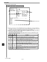
3. After moving the cursor to the kind of input signal you want with the left and right keys, select a
number with the up and down keys. Then press the ESC key. (See page 16-6 for the kinds of input
signals available for each measurement program, and see page 16-8 for details about the auxiliary
relays.)
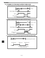
4. Move the cursor to item "
4
LOGIC SYMBOL" with the up and down keys, and press the SET key.
5. Move the cursor to the logic symbol to be used for the input signal selected in step 3, and press
the SET key.
-
The logic symbols and the input signals will be displayed as a ladder circuit.
Display example: