User Manual
User Manual
75
74
Modbus protocol is the main communication method applied in FD100 &
FD300 series converter with RS485 interfaces, which is compliant with
International Communication Standards. Centralized control can be
implemented by PC/PLC as well as superior controller to adapt specific
requirements for applications, including setting of control command,
operating frequency, modification of parameters for relevant function code,
monitoring of operating status or malfunction.
9.1 Protocol Content
Modbus, also known as serial communication protocol, has defined its
frames and format during the asynchronous transmission, including the
format of polling to the host, broadcast frames and response fames to slave
controller. The frames generated by the host included slave
address/broadcast address, executive command, data & error correction;
and the response of the slave controller has the similar frames as the host,
including confirmation of instructions, data feedback and error correction. If
any error happens when the slave controller receives the frames, or any
instruction requested by the host can't be done, it will generate a malfunction
frame and send feedback to the host.
9.1.1 Application mode
FD100 & FD300 series converter is compatible with control network
equipped with RS485 bus which has single host & multiple slave controllers.
COMMUNICATION PROTOCOL
9.1.2 Bus Structure
2. Transmission mode
RS485 hardware interface
1 Hardware interface
.
Serial & asynchronous, half-duplex transmission -TXD and RXD can
be done at the same time by either the host or the slave controller
The range of slave address should be 1~127; the number Zero stands
for broadcast communication address. Every single salve address on
the Internet is unique, which is the foundation of Modbus serial
communication.
separately, which means there are only one sender and one receiver at
a time. Data will be transmitted frame by frame in the format of
message during the serial & asynchronous communication.
3. System with single host & multiple slave controllers
9.2 Protocol Introductions
The protocol of FD300 Series Converter is a kind of serial &
asynchronous communication protocol with principal and subordinate
Modbus; there is only one device(host) could set up protocol (named "query
/command"), and the other devices(slave) can only response to the host's
"query /command" by sending data, or issue commands/instructions
according to the "query /command" from the host. The host herein mainly
refers to personal computer, industrial control facility or Programmable Logic
Controller (PLC); and the slave herein mainly refers to FD300 Series
Converter or the other control facilities with similar/same communication
protocol. The host can not only communicate with a certain
slave controller independently but also send broadcast message to all the
slave controllers. As to any independent access to the host's "query
/command", a message (called response) must be sent out from the slave
controller; however, regarding the broadcast message issued by the host, it's
not necessary for the slave controller to send feedback to the host.
9.3 Frame Structure
The data format of Modbus communication protocol applied in the
FD300 Series Converter is RTU mode (Remote Terminal Unit)
In the RTU mode, the format of each byte is as follow: encoding system
-8-bit binary system, there are two hexadecimal characters included in every
8-bit frame (hexadecimal characters include 0~9 & A~F). The transmission of
new frame will always be restarted with a interval of 3.5 bytes transmission
time. When it's connected with the Internet of which transmission rate is
calculated by Baud rate, 3.5-byte transmission time is easy to be controlled.
The data fields of transmission will be sent in sequence as below: slave
address - operating command code - data & CRC check word; and
transmission byte of each field are hexadecimal (0~9, A~F). The networking
devices will always monitor the operation of communication bus; when the
first domain (address information) is received, it will be confirmed again by
each networking device; when the transmission of last byte is done, there will
be a interval of 3.5 bytes transmission time to identify the end of this frame.
After that, transmission of new frame will be started again.
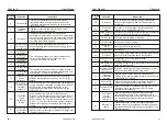
P1-00
Motor type
selection
0: General asynchronous motor
1: Variable frequency asynchronous
motor
Default
:
1
Motor rated
power
0.1kW
〜
1000.0kW
depending
Motor rated
voltage
1V
〜
2000V
depending
Motor rated
current
0.1A
〜
655.35A
depend
Motor rated
frequency
0.01Hz
〜
Maximum frequency
depend
Motor rated
speed
1rpm
〜
65535rpm
Depend
P1: First motor parameter
P1-01
P1-02
P1-03
P1-04
P1-05
The above function code is the motor parameter, and the relevant
parameters are accurately set according to the motor nameplate.
In order to obtain better VF or vector control performance, motor
parameter tuning is required, and the accuracy of the adjustment result is
closely related to the correct setting of the motor nameplate parameters.
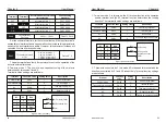
Asynchronous motor
stator resistance
0.001Ω
〜
65.535Ω
Tuning parameter
Asynchronous motor
rotor resistance
0.001Ω
〜
65.535Ω
Tuning parameter
Asynchronous motor
leakage inductance
0.01mH
〜
655.35mH
Tuning parameter
Asynchronous motor
mutual inductance
0.1mH
〜
6553.5mH
Tuning parameter
Asynchronous motor
no-load current
0.01A
〜
P1-03
Tuning parameter
P1-06
P1-07
P1-08
P1-09
P1-10
P1-06~P1-10 are the parameters of the asynchronous motor. These
parameters are generally not on the motor nameplate and need to be
automatically tuned by the inverter. Among them, "asynchronous motor static
tuning" can only obtain three parameters P1-06~P1-08, and "integrated
tuning of asynchronous motor" can obtain encoder phase sequence and
current loop PI in addition to all five parameters here. Parameters, etc.
When changing the rated power of the motor (P1-01) or the rated voltage
of the motor (P1-02), the inverter will automatically modify the P1-06~P1-10
parameter values and restore these five parameters to the common standard
Y series motor parameters. If the asynchronous motor cannot be tuned at the
site, you can enter the corresponding function code according to the
parameters provided by the motor manufacturer.
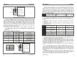
P1-27
Encoder line number
1
〜
65535
Default
:
1024
Set the number of pulses per revolution of the ABZ incremental encoder.
In the speed sensor vector control mode, the encoder pulse number must be
set correctly, otherwise the motor will not operate normally.
P1-30
ABZ incremental
encoder AB phase
sequence
0: forward 1: reverse
Default
:
0
When the asynchronous motor is fully tuned, the AB phase sequence of
the ABZ encoder can be obtained.
This function code is used to set the phase sequence of the ABZ
incremental encoder AB signal.
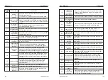
P1-31
Encoder
mounting angle
0.0
〜
359.9°
Default
:
0.0°
UVW encoder UVW
phase sequence
0: positive
1: reverse
Default
:
0
UVW encoder offset
angle
0.0
〜
359.9°
Default
:
0.0°
Rotary transformer
pole pair
1
〜
65535
Default
:
1
P1-32
P1-33
P1-34
The resolver is extremely logarithmic. When using this encoder, the polar
logarithm parameter must be set correctly.
Speed feedback PG
disconnection
detection time
0.0
:
No action
0.1s
〜
10.0s
Default
:
0
P1-36
It is used to set the detection time of the encoder disconnection fault.
When set to 0.0s, the inverter does not detect the encoder disconnection
fault. When the inverter detects a disconnection fault and the duration
exceeds the set time of P1-36, the inverter alarms ERR20.
Tuning selection
0: No auto-tuning
1: Static auto-tuning
2: Complete auto-tuning
3: Static full auto-tuning
Default
:
0
P1-37
0
:
No operation, Auto-tuning is prohibited.
1 : Static auto-tuning, suitable for asynchronous motors and where the load
is not easy to disengage and cannot be fully tuned.
Chapter 6
Chapter 6


