Deviation limit
of PI control
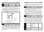
Deviation limit of PI control defines the comparison between PI
system output and maximum deviation value which is limited by closed-loop
set value. As is shown in the graph, PI regulator is shut down while it's within
deviation limit. The precision and stability of PI system can be improved by
setting this function code properly.
Sampling period
(T)
Sampling period (T) means sampling period of feedback quantity;
operation is performed by regulator once every one sampling period. The
longer sampling period is, the slower response will be.
The feedback variable of PI can be always detected by system; if
feedback variable is less than the detected value of feedback dis-connection,
system will consider feedback signal to be disconnected by default; if
feedback variable is still less than the detected value of feedback
disconnection while actual time is more than the time for detecting feedback
disconnection, PIE can be detected and sent out by the system.
0.00~2.00
Default:
0.02
P7-06
0.1
~
100.0s
Default:
0.02s
P7-07
Detected value
of feedback
disconnection
0.00
~
5.00
Default:
0.0
P7-08
Time for detecting
feedback
disconnection
0.0
~
100.0s
Default:
10.0s
P7-09
Feedback variable
Deviation limit
Output Frequency
Time
Time
Present value
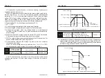
Dormancy function description: when the back pressure value >
dormancy pressure (P7-13), the frequency of running < dormancy frequency
(P7-14). Waiting for the time of sleep (P7-12), began to sleep. When the
pressure of the feedback < wake up pressure (P7-15), will cease to
dormancy, inverter will run again.
1.1 Dormancy frequency (P7-14) Settings:
1.2 dormancy pressure (P7-13) set: dormancy pressure value slightly
smaller than the target value.
1.3 when a dormant frequency P7-14 = 0 or resting pressure P7-13 = 0,
don't start the sleep function.
In under the condition of no water or gas, make the inverter running in the PID
control mode (P0-01 = 0 or 1), start the inverter. Observation line pressure,
slowly increase the frequency to the target according to user's requirements,
record the current operating frequency after downtime. Set the dormant
frequency (P7-14) just above the record frequency of 1-3 hz or so.
Sleep time
0
~
3000s
600
P7-12
Dormancy pressure
0
~
50.0Hz
0
P7-14
P7-13
P7-15
Dormancy frequency
Wake up the pressure
0
~
10.00
0
~
10.00
0
0
P8: Simple PLC and Multispeed Parameters
Program run
mode
0 : Disabled
1 : Program stop after one-cycle running
2 : Program operates as last program runs
after one-cycle running
3 : Circulatory running of program
Default: 0
P8-00
0: Disabled
1: Program stop after one-cycle running
2: Program operates as last program runs after one-cycle running
Converter will be stopped automatically after one-cycle running; only after run
command is entered again will it be started.
The operating frequency and direction in the last program will be remained to the end
after one-cycle running.
The next cycle of operation will be proceeded by converter automatically right after
one-cycle running; system will not be shut down until stop command is received.
3: Circulatory running of program
57
56
A0: Group Torque control parameter
Parameter
Name
Setting Range
Default
Prope-
rty
Modbus
Address
Fun-
ction
Code
A0-00
Speed/torque
control
selection
0
●
A0-01
Torque setting
source in
torque control
0
●
A0-03
Torque digital
setting in
torque control
-200.0%
〜
200.0%
150.0%
A0-05
Forward
maximum
frequency in
torque control
0.00Hz
〜
Maximum frequency
50.00Hz
A0-06
Reverse
maximum
frequency in
torque control
0.00Hz
〜
Maximum frequency
50.00Hz
A0-07
Acceleration
time in
torque control
0.00s
〜
65000s
0.00s
A0-08
Deceleration
time in
torque control
0.00s
〜
65000s
0.00s
0 : speed control
1 : torque control
0 : Digital setting (A0-03)
1 : AI1 2 : AI2 3 : AI3
4 : Pulse setting
5 : Communication reference
6 : MIN (AI1, AI2)
7 : MAX (AI1, AI2)
(1-7 options full scale,
Corresponding to A0-03
number setting)
A5: Control optimization parameter
Parameter
Name
Setting Range
Default
Prope-
rty
Modbus
Address
Fun-
ction
Code
A5-00
DPWM
switchover
frequency
upper limit
5.00Hz
〜
Maximum frequency
8.00Hz
A5-01
PWM
modulation
method
0
A5-02
Dead zone
compensation
mode selection
1
A5-03
Random
PWM depth
0 : Invalid
1
〜
10 : Random PWM depth
0
A5-04
Rapid current
limit
0 : Invalid
1
: Valid
1
A5-05
Current
detection
compensation
0
〜
100
0
A5-06
Under voltage
threshold
60.0%
〜
140.0%
100.0%
A5-07
SVC
optimization
mode selection
2
A5-08
Dead time
adjustment
100%
〜
200%
150%
●
A5-09
Overvoltage
threshold
200.0V
〜
2200.0V
Model
dependent
●
0 : Asynchronous modulation
1 : Synchronous modulation
0 : No compensation
1 : Compensation mode 1
2 : Compensation mode 2
Fun-
ction
Code
Parameter
Name
Setting range
Default
Prope-
rty
Modbus
Address
0 : Not optimized
1 : Optimized mode 1
2 : Optimized mode 2
A6: AI Curve setting
Fun-
ction
Code
Parameter
Name
Setting range
Default
Prope-
rty
Modbus
Address
A6-00
AI curve 4
minimum input
-10.00V
〜
A6-02
0.00V
A6-01
AI curve 4
minimum input
correspon-
dence setting
-100.0%
〜
+100.0%
0.0%
A6-02
AI curve 4
inflection point
1 input
A6-00
〜
A6-04
3.00V
A6-03
AI curve 4
inflection point
1 input
correspon-
ding setting
-100.0%
〜
+100.0%
30.0%
A6-04
AI curve 4
inflection point
2 input
A6-02
〜
A6-06
6.00V
A6-05
AI curve 4
inflection point
2 input
correspon-
ding setting
-100.0%
〜
+100.0%
60.0%
User Manual
Chapter 5
User Manual
Chapter 5
○
○
○
○
○
○
○
○
○
○
○
○
○
○
○
○
○
○
40961
40962
40964
40966
40967
40968
40969
42241
42242
42243
42244
42245
42246
42247
42248
42249
42250
42497
42498
42499
42500
42501
42502


